Series 1100 trouble shooting guide
![]() 1. Lost Sync With Distribution Board Message
1. Lost Sync With Distribution Board Message
![]() 3. Loosing Zero
3. Loosing Zero
![]() 7. Backing Up The Configuration File Before Loading New
Software
7. Backing Up The Configuration File Before Loading New
Software
Chapter 1.
Lost Sync with Distribution Board
1. Check to see
if the LED’s labeled L1, L2, L3 on the distribution board
in the back left corner are illuminated. If the LED’s are not on, please check
the voltage on the P1 Plug located on the back left corner of the
distribution board. Turn the 110 VAC power off and remove this cable from the
distribution board. Turn the 110VAC power back on and check from the black wire
in connection number 6 to the red wire in connection number 5 you must
have at least 5.1 – 5.2 VDC across these 2 wires. Next check from the
same black wire to the other 2 wires, you must have + 15.01 to
+15.1VDC and - 15.01 to -15.1VDC. If the voltages are correct with the cable
removed, turn the power back off and reconnect the cable. Turn the power back
on and recheck for the same voltages and go to step 1. If any of the voltages
are wrong please order part # ![]() 31901232 from Anilam or from your local Distributor.
31901232 from Anilam or from your local Distributor.
Step 1. If the voltages change there is a problem either with the distribution board, or one of the cables connected to the distribution board.
Step 2. Turn the 110 VAC power off again.
Step 3. Remove all of the cables from the distribution board except for the P1
Plug. After removing all of the cables turn the 110VAC power back on
and check for the proper voltage again. Did the voltage remain? If yes, go to
step 4. If no, the problem is a bad Distribution board part # ![]() 31900406S.
Contact your local Distributor or Anilam to get the replacement board.
31900406S.
Contact your local Distributor or Anilam to get the replacement board.
Step 4. If the voltage comes back 1 or more of the cables removed has a problem.
Step 5. If the voltage is there, then turn off the 110VAC power again and one at a time connect the cables that you previously disconnected, turn the power back on and recheck for the proper voltages.
Step 6. Repeat step 5 each time until the problem returns. Once the problem returns, turn the power off and remove the problem cable. Continue doing the same process until you determine the cable or cables causing the problem.
Step 7. Once you know which cable(s) that is causing the problem, check to see what the other end is connected to and unplug the cable if possible.
Step 8. With the cable unplugged from the item opposite from the distribution board, reconnect the cable to the distribution board and turn on the 110VAC power. Did the problem go away? If yes, then the item you unplugged is bad. Contact Anilam or your local Distributor to get the defective part replaced. If no, the problem is in the cable itself. Check if the cable is cut and shorting to ground. Repair if possible, otherwise contact Anilam or your local Distributor to obtain the replacement cable. Repeat steps 7 and 8 until you know which parts are the defective items.
If your voltage was fine with everything plugged in, check to see if you happen to have a screw lying on top of the distribution board. This screw may have fallen out of the spindle overload, labeled 13. This screw has over time loosened up and fallen onto the distribution board causing this symptom.
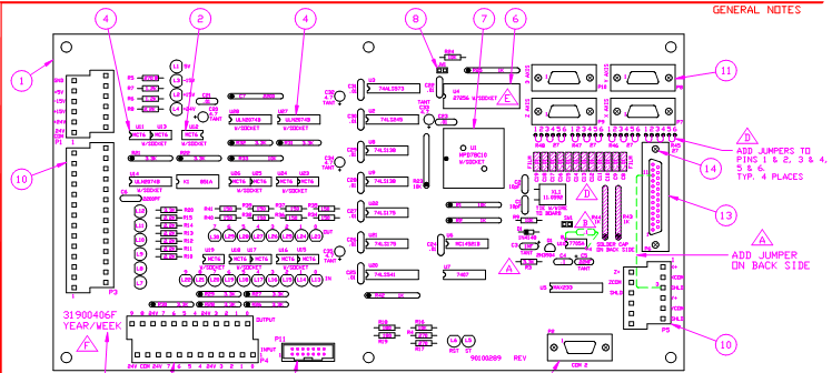
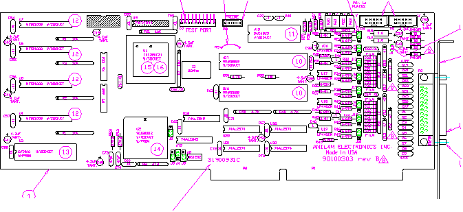
The
following drawing is an S1100 distribution board Part # ![]() 31900406s:
31900406s:
The next possible problem could be a bad connection, from the computer com 2 cable to the distribution board. To check the computers' com 2 port do the following:
Step 1. Locate your diagnostic disk that should be located in the programming manual.
Step 2. Turn off the 110 VAC power and insert the diagnostic disk into the computer.
Step 3. Open the computer cabinet main door and remove the cable labeled com 2.
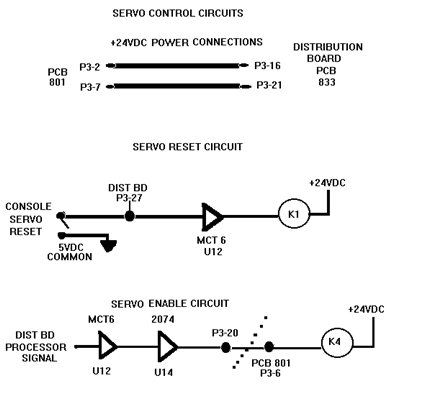
Step 4. After removing the cable labeled com 2, you need to get a piece of wire and jump together terminals 2 and 3 on the com 2 connector. The following is a layout of the com 2 connector located on the CPU board.
Step 5. Turn on the 110 VAC power and wait for the diagnostic disk to boot. After the computer boots from the diagnostic disk, select F1 key in order to run the software.
Step 6. Select TESTS from the top menu choices and press the Enter key.
Step 7. Select CPU & RELATED SYSTEM TESTS and press the Enter key.
Step 8. Select SERIAL I/O and press the Enter key.
Step 9. Select EXTERNAL: ONE PORT SELECTABLE and press the Enter Key.
Step 10. Select COM 2, making sure the jumper is installed across pins 2 & 3 on the com 2 port and press the Enter key. The test should come back with a passed message after sending and receiving information to itself. If it does say test passed then reconnect the cable to the com 2 port and remove it from the Distribution board. Note: This step can be done with power left on! Now on the cable that you just removed from the distribution board you need to jump pins 2 & 3 on the cable and repeat step 9. If the test does not pass for either, then contact Anilam or your local Distributor for more advice.
If everything so far checks out then try reloading the software as a last resort. In some versions of 1100 software a question might be asked “Overwrite configuration using Defaults Y or N” answer NO! After the software has completed loading, recheck and see if the problem persists. If it does please contact Anilam for any more suggestions.
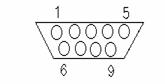
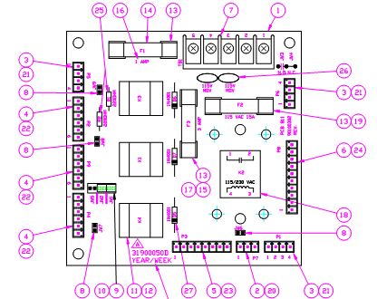
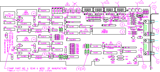
The
following drawing is the PC 801 print for 2 axis double box and 3 axis systems
only Part
# ![]() 31500321s!
31500321s!
CHAPTER 2
Servo Won’t Energize
1. Is this a 2 axis single box computer system?
A. If it is go to the 2 axis single box servo section located later on in this chapter.
B. If it is either a 2 axis double box or a 3 axis double box system then continue.
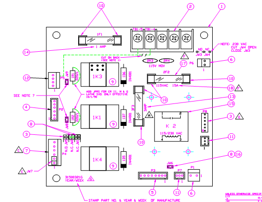
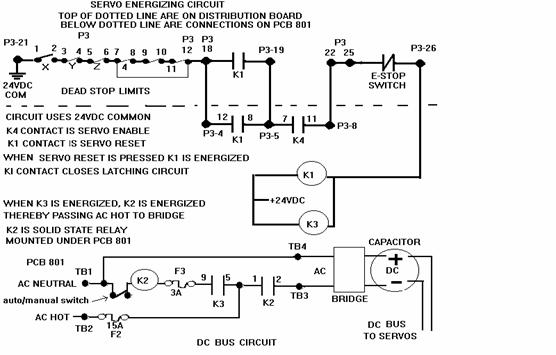
The following drawing is the servo turn on circuit:
2. Reboot the computer and check the messages. The following message is what you should see. M 2 Motion Brd + D 2 Distrib. Detected.
A. Do you have this message?
1. If no, Did the message say M 2 Motion Brd + Non Distrib. system Detected. If this is the message go to section 1 lost sync. and follow instructions there.
2. If you had the correct original message then open the servo box door and check on the distribution board front left hand corner LED’s L7,L8,L9, and L12, must be illuminated. If any of these are out check the limit switch that corresponds to the LED. L7 usually is the X limit switch, L8 usually is the Y axis limit switch, and L9 usually is the Z axis limit switch. If X axis is the problem then all 4 LEDs will be off. However please check the 4 LEDs on the back left corner of the distribution board labeled L1,L2,L3, and L4, these must be illuminated !
3. Is the 24VDC LED labeled L4 illuminated? If yes go to step 4. Otherwise continue.
A. If the answer is no please check the Pc 801 board. On this board there is a 1 amp fuse (F1) which controls the 24VDC output. If the fuse is OK please check for the 24VDC right on the 24 volt power supply that is plugged into to PC 801 board P5 connector. Check across the Yellow and Blue colored wires. If you do not have any voltage please unplug the F1 fuse located on the PC 801 board and recheck. If the voltage comes back then there is an external short causing the voltage to drop away move to step B in this section otherwise continue with the next step.
1. If the voltage did not come back please check the black and white wire
across the transformer of the 24 volt supply. You should see 110VAC across these
two points. If you have 110VAC then your power supply is bad order part # ![]() 31500190s from your local Anilam distributor or from Anilam
directly.
31500190s from your local Anilam distributor or from Anilam
directly.
2. If the 110VAC was not there please check the white 15 amp slo-blo fuse
located on the PC 801 board; it is labeled F2. There should be 110VAC Hot on both sides of
the fuse in reference to TB1-1. If you have no voltage on either side of
the fuse check TB1-1 and TB1-2 for 110VAC. If you have the
voltage at these points you have blown a trace on the PC 801 board. Please
either repair the wire trace or order a new PC 801 board. The part # is ![]() 31500321s.
31500321s.
3. If there was no voltage at TB1-1 to TB1-2 please check the terminal strip that is located above the PC 801 board across the terminals labeled 0 and 110. There should be 110VAC across those to points. If the voltage isn’t there then it has to be a wiring connection problem on the terminal strip jumping the voltage from one contact point to the next point. Please repair as necessary and recheck if everything now works correctly. If everything works do not go to step B.
B. If the voltage came back after removing the F1 fuse go to the distribution board and remove the P4 plug. Replace the fuse and recheck. If the voltage is still there the short is caused by something wired to the P4 cable. Check for shorts in the cable and check for shorting to ground in the same cable. If the problem persists please contact your local Anilam distributor or Anilam directly.
4. At this point you should have L1,L2,L3,L4,L7,L8,L9, and L12 LEDs illuminated ! If all of these are on but
the servo still will not energize please check the voltage from the PC 801
board connections TB1-4 and TB1-5 for 110VAC after you press the reset button.
If you have the 110VAC across the terminals TB1-4 and TB1-5 follow the wires to
the fuse or fuses and see if you have 110VAC on both sides of the fuses. Next
check the large blue capacitor, see if you have 160VDC across the 2 screws
on top of the capacitor. If you do not have the voltage you have a bad bridge
rectifier part # ![]() 90500605 or a broken wire or bad
crimp.
90500605 or a broken wire or bad
crimp.
A. If the 160VDC across 2 screws on the capacitor is present, look at the drive cards. On the drive card there is a small RED Fault light. Is the fault light on?
1. If the light is on, is it illuminated on all of the drive cards?
A. If at least 1 drive card fault light is off, then this one axis should be OK. Try moving each axis into the one good axis and energize the drives again. Does the LED on this board illuminate and stay on or does it go back out?
1. If it stays on this drive card is bad. You need to order a new one. If
this drive card says ANILAM on the sticker of the drive card itself
Anilam’s part # is ![]() 31500966s. Keep checking all axis the
same way until we know how many drive cards are working. If the drive card does
not say Anilam then you must contact the machine manufacturer or the
distributor that sold you the equipment. This drive card is not an Anilam part.
31500966s. Keep checking all axis the
same way until we know how many drive cards are working. If the drive card does
not say Anilam then you must contact the machine manufacturer or the
distributor that sold you the equipment. This drive card is not an Anilam part.
2. If the light went out then you should be able to move the axis that this board is plugged into. If you can move the axis back and forth, then the card is OK, we need to check all the boards the same way.
A. We want to next check the motor cable that is screwed into the servo box for the axis that caused the fault lights to come on. We need to check for any shorts to the casing of the motor. We also need to check for any shorts in the cable to any other wires in the cable. If you find what seems to be a short in a cable unscrew the other end from the motor and recheck the same way.
1. Did the short go away? If yes, then check the motor. If no, then check the 1 good cable the same way and compare results. All axis should have the same characteristics in the motor and motor cable wiring. Once we have found the bad item that will either be the motor or the motor cable or both, continue checking the remaining axis the same way.
2. Once we know what items are good, or at least do not have any shorts, take your good drive card and put it in the axis that wasn’t working and energize the drive. Did the fault light come on and go back off? If yes, can you move the axis in both directions? If you can great! Check all axis the same way. Once you have determined what items caused the problem please contact your local Anilam distributor or Anilam directly to get the replacement parts.
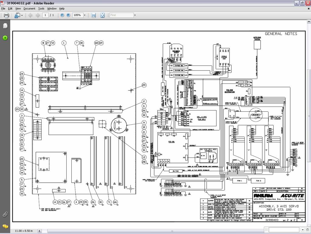
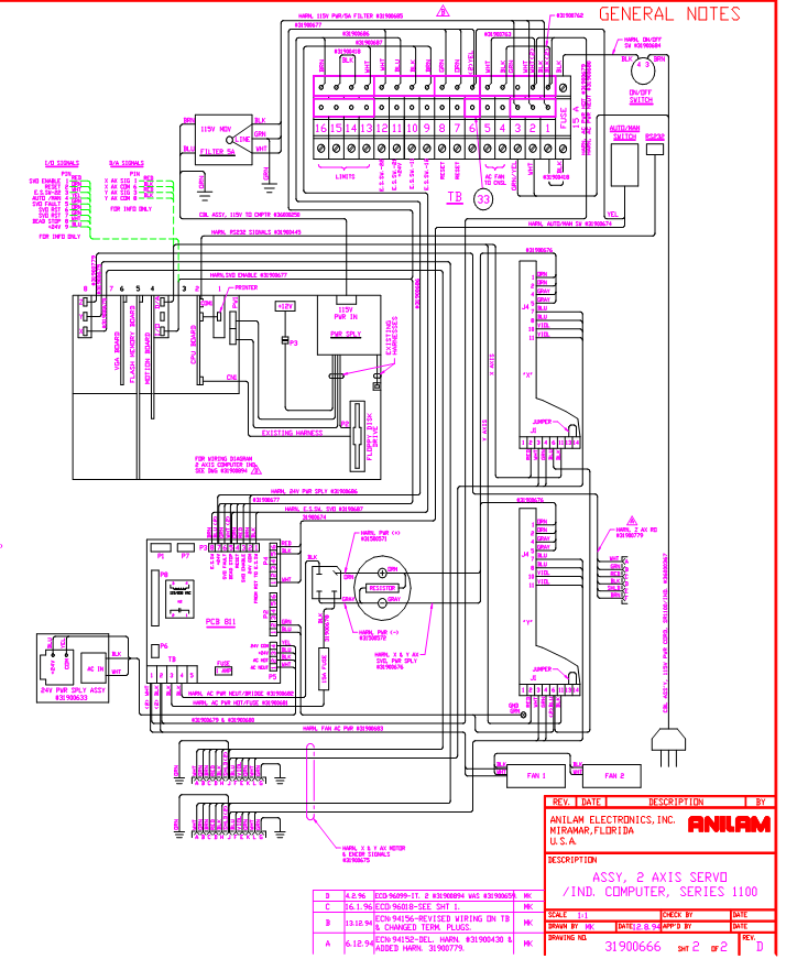
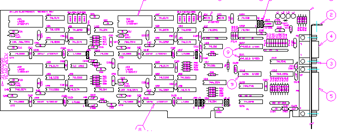
![]() This drawing is the overall
wiring diagram for a Double box system:
This drawing is the overall
wiring diagram for a Double box system:
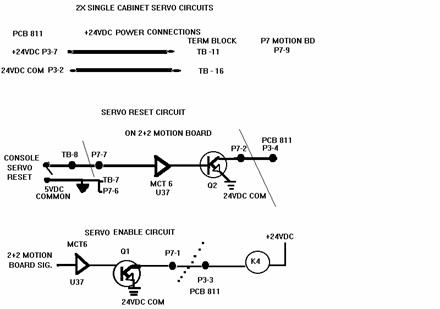
1.2 axis single box system section-
A. The following drawing describes the servo turn on circuit.
2.
The servo turn on circuit comes from the motion control board Part # ![]() 31900658s.
31900658s.
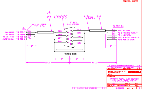
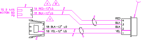
The following drawing is the I/O harness from motion control board:
The following information is in regards to the LED's on the 2 + 2 board, LED 1 = +24 vdc is present, LED 2 = servo is on/off, (after servo reset LED 2 turns off), Led 3 = servo enable, (when the e-stop is pulled out this led should be on), Led 4 = auto/manual switch (when the LED is off you are in auto mode; when the LED is on you are in manual mode)!
A. Do you have 24VDC from the 24 volt power supply?
1. Check on the PC 811 board P5-3 (+24VDC) and P5-4 (24VDC common).
A. If you have 24 volts across those two points leave your black meter lead connected to 24VDC common and check the F1 fuse on both sides. If you have voltage on one side but not the other you have a blown fuse. Replace with a 1 amp slo-blo fuse.
B. If you do not have the 24VDC unplug the F1 fuse on the PC 811 board. Check again for 24VDC across P5-3 and P5-4 on the PC 811 board.
C. If the voltage is now present then you have a short on the 24 volt positive
output to ground. Remove the cable on the PC 811 board labeled P3. Put back in
the fuse and see if the voltage still remains OK. If the voltage is still
present then the short is external from this board. If the voltage drops away
check for foreign debris on the PC 811 board or replace the board. Anilam’s
part # is ![]() 31501002s.
31501002s.
D. If the short is external remove the cable from the motion control board and reconnect the cable on the PC 811 board labeled P3. Is the voltage still OK?
1. If the voltage drops away push in the E-Stop switch. Did the voltage now come back? If the voltage returned when the E-Stop switch was pushed in the problem is located on the cable between the E-Stop switch and the motion control board. Repair or replace the cable.
E. If the voltage came back only after removing the cable from the motion
control board the problem is a bad motion control board. Anilam’s part # is ![]() 31900658s.
31900658s.
3. Does the K4 relay on the PC 811 board energize?
A. K4 relay energizes when the E-stop is pulled out and the motion board outputs the signal called servo enable.
The following drawing is the PC 811 mechanical drawing Part # 31501002s:
1. If the K4 relay does not energize check on the PC 811 Board P3-3. There should be 24VDC
common on this point in reference to PC 811 Board P3-7. If the voltage
isn’t there, go back to the Motion Control Board DB9 connector Pin 1 and Pin
9. Remove the cable at both ends and check with an ohm meter these 2 pins.
If you need look at print # ![]() 31900677. If the wiring is OK you
have a bad Motion Control Board. You would need to order Part #
31900677. If the wiring is OK you
have a bad Motion Control Board. You would need to order Part # ![]() 31900658s.
31900658s.
A. If K4 relay did energize check and make sure you are not on any limit switches.
1. You can verify that the wiring and switches are OK by checking from the PC
811 P3-7 (+24VDC) and checking to the terminal strip above the computer. The
connections to check are labeled 13 - 16. On each of the terminals you should
see 24VDC common. If the voltage is not on one of the terminals you must check
the wiring to the switch and the switch itself. Not having the voltage on the
terminal strip signifies an open in the limit switch string. This will keep the
servo from energizing. Fix the wiring or change the switch. The switch part
# is ![]() 31500651.
This switch is designed with a roller plunger single contact setup.
31500651.
This switch is designed with a roller plunger single contact setup.
2. Next take the cover off the computer. Locate the motion control board. The following LEDs need to be illuminated:
L1 = +24VDC Present
L2 = Servo Fault input
L3 = E-Stop switch OK for servo enable
If L4 LED is on the control is in manual mode. If you are in manual mode the servo most definitely will not energize.
A. If all of the lights are out this means your limit switch string is open. Please recheck wire connections for the limit switches.
B. If all the lights are on (L1-L3), remove the cable from the motion control
board. Put your meter on to ohms. Check from P7-6 to P7-7 and push the reset
button. You should get continuity across these pins if the switch is good
and the wiring is good. If the switch is bad order the main key board part # ![]() 23000095s.
If the switch was OK you have a bad motion control board. You need to order
part #
23000095s.
If the switch was OK you have a bad motion control board. You need to order
part # ![]() 31900658s.
31900658s.
4. If K4 relay energized press the reset button and see if K1 and K3 relays energize. If they do energize check on TB1-3 and TB1-4 on the PC 811 board for 110VAC.
A. If you have the voltage then go to the 15amp fuse and see if you have 110VAC on both sides of the fuse.
B. If you do not replace the fuse with another 15amp slo-blo fuse.
1. Next check the large blue capacitor, see if you have 160VDC across the
2 screws on top of the capacitor. If you do not have the voltage you have a bad
bridge rectifier part # ![]() 90500605 or a broken wire or bad
crimp.
90500605 or a broken wire or bad
crimp.
A. If the 160VDC across 2 screws on the capacitor is present, look at the drive cards. On the drive card there is a small RED Fault light. Is the fault light on?
1. If the light is on, is it illuminated on all of the drive cards?
A. If at least 1 drive card fault light is off, then this one axis should be OK. Try moving each axis into the one good axis and energize the drives again. Does the LED on this board illuminate and stay on or does it go back out?
2. If it
stays on this drive card is bad. You need to order a new one. If this drive
card says ANILAM on the sticker of the drive card itself Anilam’s
part # is ![]() 31500966s. Keep checking all axis the
same way until we know how many good and bad drive cards you are working with.
If the drive card does not say Anilam then you must contact the machine
manufacturer or the distributor that sold you the equipment. This drive card is
not an Anilam part.
31500966s. Keep checking all axis the
same way until we know how many good and bad drive cards you are working with.
If the drive card does not say Anilam then you must contact the machine
manufacturer or the distributor that sold you the equipment. This drive card is
not an Anilam part.
3. If the light went out then you should be able to move the axis that this board is plugged into. If you can move the axis back and forth, then the card is OK, we need to check all the boards the same way.
A. We want to next check the motor cable that is screwed into the servo box for the axis that caused the fault lights to come on. We need to check for any shorts to the casing of the motor. We also need to check for any shorts in the cable to any other wires in the cable. If you find what seems to be a short in a cable unscrew the other end from the motor and recheck the same way.
1. Did the short go away? If yes, then check the motor. If no, then check the 1 good cable the same way and compare results. All axis should have the same characteristics in the motor and motor cable wiring. Once we have found the bad item that will either be the motor or the motor cable or both, continue checking the remaining axis the same way.
2. Once we know what items are good, or at least do not have any shorts, take your good drive card and put it in the axis that were not working and energize the drive. Did the fault light come on and go back off? If yes, can you move the axis in both directions? If you can great! Check all axis the same way. Once you have determined what items caused the problem please contact your local Anilam distributor or Anilam directly to get the replacement parts.
5. The following drawing on the next page is the overall servo wiring diagram for single box system:
![]() PDF version of 31900666 sheet
2.
PDF version of 31900666 sheet
2.
Chapter 3
Loosing Zero
1. Is your system a 2 axis single box system? If yes check inside the computer for a loose connection on the motion board. The 5VDC to power the encoders or scales comes from the computer power supply. The cable plugs onto the motion board at location P9 see drawing below for wire connections. For a 2 axis single box system please skip step 2 in this chapter and continue with step 3.
2. For a 2 axis double box or 3 axis system the 5VDC comes from the power supply which is under the distribution board. The power supply cable plugs onto the distribution board P1 connector. If there are any questions about location of this cable refer back to Chapter 1 for the print of the distribution board. Make sure the power is turned off before you continue.
A. On some of the original distribution board systems check to see if you have R43 and R44 still mounted on the distribution board. Looking at the distribution board these resistors would be located on the right hand side of the board. On the right hand side there is a DB25 connector labeled P6. These 2 resistors would be just to the left of this connector. If these resistors are on the board, you must cut both of them off of the distribution board.
B. Check the power supply cable on the distribution board plugged onto the P1 connector. Unplug this cable with power off. Using your ohm meter check the cable P1-6 (ground) to chassis ground. There must be a connection to earth ground when this cable is unplugged! If there is no connection then add a wire to the phoenix block connection number 6. The other end of this wire mounts to the screw to the left of this connector. There should already be a wire or two under this screw.
C. Check and verify if you have a metal braided cable connecting the servo cabinet to the computer cabinet.
1. If you do not have this cable you must add a 12 gauge or 14 gauge stranded wire between cabinets. This is to tie the computer power supply and the servo power supply commons to Earth ground.
D. Turn the 110VAC power back on and leave the servo box door open. Turn on the main disconnect switch. Check the P1 plug cable that you removed from the distribution board. Check across connections P1-6 to P1-5. You must have at least 5.01VDC across these two points.
1. If you have less then 5.01VDC across these two points, go to the power supply mounted under the distribution board. On this power supply there is a little screw adjustment. While checking P1-5 to P1-6 adjust this screw which will adjust the power supply’s output. Adjust until you obtain 5.01VDC minimum to 5.1VDC maximum.
E. Turn the 110VAC power back off and reconnect the P1 cable. After connecting this cable turn back on the 110 power and recheck your system to see if you are still loosing zero.
3. The following procedure will help to determine what the problem could be.
A. Put an indicator in the spindle.
B. Touch off the indicator on to your part or something that you know is stationary and flat mounted on top of the table.
C. Zero the display and zero the axis.
D. Either write a program to move the axis away and then to return to zero or jog the axis away and then program the control to return to zero. Did the indicator and the display both say zero? If they both agree move the axis further away from zero and recheck again. Repeat this for the full length of travel for the axis.
E. Did the axis repeat to zero each time?
1. If yes, it sounds like you have fixed the problem. Rerun your program that you originally found you were loosing zero with. See if you are still loosing zero. If your problem has gone away do not continue to step 4.
4. After doing the repeatability test are you still loosing zero?
A. If yes, do you have scales or encoders on this axis?
1. For a scale system check and clean the scale using either denatured alcohol or acetone and a cotton swab or lint free cloth and wipe the glass which is located up in the metal extrusion. Wipe this glass on both sides from one end to the other. After doing this repeat step 3.
2. For an encoder system please check to see where the encoder is mounted. On
some systems the encoder is built into the motor. On other systems you may have
an encoder mounted either to the back of the motor or mounted to the ballscrew.
If the encoder is part of the motor and is not easily swapped to another axis,
then swap motors to see if the problem will move with the motor into a working
axis. If swapping the motor the problem moved to the other axis, then the
problem is in the encoder which is built into the motor. Check on the label
which is mounted on the motor, what the motor is rated for. For a torque
rating of 3.0 NM the Anilam part number is ![]() 37000117.
For a torque rating of 4.5 NM the Anilam’s part number is
37000117.
For a torque rating of 4.5 NM the Anilam’s part number is ![]() 37000225.
For any other motors which don’t have these torque ratings you must contact the
Distributor who sold you the system.
37000225.
For any other motors which don’t have these torque ratings you must contact the
Distributor who sold you the system.
A. If the encoder is separately mounted and is not mounted inside the motor, check the coupling for loose screws. You can also swap the encoder usually from one axis to another. Check the markings on the encoder. The model number typically is marked L25G followed by some more numbers. If the 2 encoders from one axis to the other are marked the same, you can swap them and see if the problem now moves to the other axis. Repeat step 3 to verify if the problem moved.
B. If the problem moved to the other axis, you now know what the problem is. Contact your local Anilam Distributor or Anilam directly to order the replacement part.
5. Did the problem stay in the original axis? If it did then check the wiring connections from the motion board to the distribution. If you have the encoder style which is built into the motor you can swap the motor cable to see if the problem is in the cable itself.
A. If after swapping the motor cable the problem remains in the same axis, it sounds like the motion board failed. Turn off the 110VAC power and open the computer cabinet. Please read the following document which explains the proper procedure to discharge static electricity.

The electrical components contained in this package can be damaged by static electrical charges. Please observe the following precautions:
· Before touching any part of the system or any of its components, discharge your body’s electrostatic charge by touching a grounded metal surface.
· Before opening the protective bag, discharge it’s electrostatic charge by touching it to a grounded metal surface.
· Do not remove the electrical component from its anti-static bag until you are ready to install it.
· Do not lay an electrical component on top of its protective bag (only the inside is protected).
· Handle electrical components by the edges and metal mounting brackets. Avoid touching the electrical components or the edge connectors.
· Keep electrical components away from plastic, vinyl, Styrofoam, furs and cardboard.
· Wear a grounding wrist strap throughout the installation, procedure if one is available.
Remove the motion control board only after you touch the cabinet to discharge any static electricity which may have built up on your body. After removing this board try not to touch any of the electrical components on the board. On this board there is an Anilam part number silk screened on it. Please locate this number and write it down.
A. Look on this board there are some potentiometers located on the front edge of the board. How many potentiometers are on the front edge? The following describes the part numbers that are silk screened on the board with the amount of potentiometers mounted on the board.
1. 90100274
with 6 potentiometers = ![]() 31900510s.
31900510s.
2. 90100274 with 8 potentiometers = 31900290s.
3.
90100303 = ![]() 31900804s.
31900804s.
The above part numbers beginning with 319 are the part numbers you want to order.
NOTE: If ordering part number ![]() 31900804s
Anilam must know what version software is loaded on the machine. Anilam also
needs to know what options if any are also loaded on the machine! The software
and firmware MUST match!
31900804s
Anilam must know what version software is loaded on the machine. Anilam also
needs to know what options if any are also loaded on the machine! The software
and firmware MUST match!
Chapter 4
Intermittent Shut Downs
1. Are you loosing zero after the servo shuts down? If the answer is yes, go to Chapter 3.
2. Are you getting a Lost sync with distribution board message? If yes, go to Chapter 1.
3. Does the shut down occur when a particular axis is run only?
A. If there is a particular axis that when moved causes the servo to shut off, check to see if the axis counts. If it counts continue if it does not count go to Chapter 3.
B. Does the motor for the axis that is shutting down have torque? If the answer is yes go to step 4, otherwise continue.
1. Energize the servo and try to move the ballscrew by hand. Normally the motor should resist you and not allow you to hand crank it.
2. Check to see if the axis causing the problem has the little red fault light illuminated.
A. If at least 1 drive card fault light is off, then this one axis should be OK. Try moving each axis into the one good axis and energize the drives again. Does the LED on this board illuminate and stay on or does it go back out?
1. If it stays on this drive card is bad. You need to order a new one. If
this drive card says ANILAM on the sticker of the drive card itself
Anilam’s part # is ![]() 31500966s. Keep checking all axis the
same way until we know how many drive cards are working. If the drive card does
not say Anilam then you must contact the machine manufacturer or the
distributor that sold you the equipment. This drive card is not an Anilam part.
31500966s. Keep checking all axis the
same way until we know how many drive cards are working. If the drive card does
not say Anilam then you must contact the machine manufacturer or the
distributor that sold you the equipment. This drive card is not an Anilam part.
2. If the light went out then you should be able to move the axis that this board is plugged into. If you can move the axis back and forth, then the card is OK, we need to check all the boards the same way.
A. We want to next check the motor cable that is screwed into the servo box for the axis that caused the fault lights to come on. We need to check for any shorts to the casing of the motor. We also need to check for any shorts in the cable to any other wires in the cable. If you find what seems to be a short in a cable unscrew the other end from the motor and recheck the same way.
1. Did the short go away? If yes, then check the motor. If no, then check the 1 good cable the same way and compare results. All axis should have the same characteristics in the motor and motor cable wiring. Once we have found the bad item that will either be the motor or the motor cable or both, continue checking the remaining axis the same way.
2. Once we know what items are good, or at least do not have any shorts, take your good drive card and put it in the axis that wasn’t working and energize the drive. Did the fault light come on and go back off? If yes, can you move the axis in both directions? If you can great! Check all axis the same way. Once you have determined what items caused the problem please contact your local Anilam distributor or Anilam directly to get the replacement parts.
4. Does the axis that is shutting down work in feed but just not in rapid? If the answer is yes please check the amperage draw on that motor.
A. Locate in your programming manual a little PC board marked 31900476. Take this board to the machine and do the following test.
GIB ADJUSTING
1. PUSH IN THE EMERGENCY STOP BUTTON NOW TO DE-ENERGIZE THE DC
POWER SUPPLY BEFORE PROCEEDING! Open the servo box door.
2. The three servo cards have a large plug on the top edge.
Refer to the DRVCARD drawing at the end of this procedure for
a simplified drawing of the servo cards. Remove the ARMATURE/DC
· BUS PLUG from the top connector. Install the circuit board P/N 31900476 on the pins on the card being sure to place it so
that the two loops sticking out from the board (P/N
31900476) are at the lower edge of the board. Connect a
DIGITAL ammeter to the two loops on the board
(P/N 31900476) with one meter lead attached to each. Set the
meter to the 10 AMP DC scale now. This places the meter in
series with the motor armature. This will allow you to measure
the amperage when the slide is moving. This is required prior
to setup to insure that there are no tight spots in the ways
or alignment problems.
3. Replace the ARMATURE/DC BUS plug from the harness onto the
pins facing you on the P/N 31900476 board. BE SURE THAT THE
ORANGE WIRES ARE AT THE TOP OF THE PLUG AND THE LAVENDER ONES
ARE AT THE BOTTOM.
4. Start the control and move the axis being checked from extreme
to extreme.
· This should be done in a FEED mode to allow sufficient time to monitor the meter. Note the amperage throughout the travel. Now change to RAPID mode and repeat step 4. If the amperage in rapid is around 7-8 amps, there is a definite problem. Loosen the GIB a couple of turns and try the same test again. Slowly tighten the GIB until a .25 amp rise is seen. Now back off the GIB 1/2 turn. This should be approximately the correct setting for the GIB. SETTING THE GIBS TOO TIGHT WILL ADVERSELY
AFFECT THE MACHINE ACCURACY. A SURE SIGN OF TOO TIGHT A GIB IS
EXCESSIVE BALL SCREW LOST MOTION.
5. Repeat this for the next axis to be checked. Bear in mind that
the amperage seen on X axis will increase at either end. This
is caused by the tremendous weight shift as the table reaches
either end. Any large shift in amperage on Y axis could be
caused by tight ways at either end ( machine worn in center of
the travel ) or incorrect alignment of the ball screw.
6. Z axis should be monitored for changes in amperage while
moving. There are no gibs to set but any extreme changes will
show out of alignment of the casting mounting.
B. If the drive still shuts down after you have checked
the amperage on the motor, go to the servo card
alignment section.
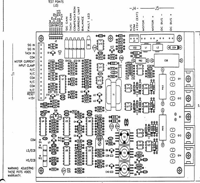
The
following drawing is the Glentek Drive Card ![]() 31500966S:
31500966S:
Chapter 5
Servo Card Alignment
1.
Refer to the servo drive card drawing on the previous page. Is your drive card
the same as the one in the drawing? On the back of this board there will be an
Anilam Label with the part # ![]() 31500966 on it.
31500966 on it.
A. If the Drive card you are about to adjust is not this board. Please contact the Distributor who sold the system to you to find out how to balance this particular board. Anilam did not supply this board and therefore can not tell you the easiest way to balance this board!
B. If the board does look like the drawing and is labeled with part # ![]() 31500966
then please continue.
31500966
then please continue.
1. Push in the Emergency Stop button. Turn off the 110VAC power. Open all doors both on the servo drive cabinet and the computer cabinet.
2. Remove the cover on the computer.
3. Go to the servo drive card and locate test points 1 & 2. Get your volt meter and change to DC Millivolts.
4. Put your meter leads onto the X drive card across test points 1 & 2.
5. Go back over to the computer and check what style motion board you have! There are 3 different styles of motion boards in the field.
Please note the difference between each of the three boards. The DSP has only a DB25 connector. The 2+2 board has 2 DB9 connectors. The original 3 axis board has 1 DB25 and 1 DB9 connector on it.
The
following drawing is the DSP Board part # ![]() 31900804s.
31900804s.
The
following drawing is for 2+2 board part # ![]() 31900658s.
31900658s.
The
following drawing is for 3 axis Motion board part # ![]() 31900510s.
31900510s.
6. If you have a DSP style board system check your programming manual. There is a section specifically on how to balance a DSP style system. Please refer to this manual.
7. If you have either a 2 axis 2+2 board or the 3 axis board do the following procedure.
A. Go to your programming manual and locate the Diagnostic disk.
B. Put the disk into Drive ‘A’ and boot on the disk.
C. Press the F1 key.
D. Using your arrow key highlight Motion and push the Enter key.
E. Pull out the Emergency Stop switch and press the reset button.
E. Press the F2 key (setup).
F. Highlight Analog Balance and press the Enter Key.
G. Press the F2 key for balancing the X axis.
H. Look at your volt meter you need to adjust the motion board to achieve 0 Millivolts DC.
1. R1A = X axis adjustment.
2. R1B = Y axis adjustment.
3. R1C = Z axis adjustment.
I. While looking at your volt meter go to the motion board and adjust the appropriate potentiometer.
J. After adjusting the motion board move the meter lead from test point 2 to test point 3 leaving the other meter lead still connected to test point 1 on the drive card.
K. Look at the drive card your meter is connected to. Locate the potentiometer labeled BAL (RV5). Adjust the BAL potentiometer until your meter displays 0 Millivolts DC.
L. Press the F3 key which selects the Y axis.
M. Remove your meter leads from the X axis drive card and place 1 meter lead onto the Y axis drive board test point 1. Put the other meter lead onto the Y axis drive card test point 2.
N. Repeat steps H through K in this section!
O. When Y axis is adjusted if you have a Z axis press the F4 key which selects the Z axis otherwise, go to step 8.
P. Remove your meter leads from the Y axis drive card and place 1 meter lead onto the Z axis drive board test point 1. Put the other meter lead onto the Z axis drive card test point 2.
Q. Repeat steps H through K in this section!
8. Adjusting the signal for each axis do the following steps.
A. Press the F10 key twice in a row.
B. Using the up and down arrow keys highlight Signal Gain and press the Enter Key.
C. Press the F2 key to run the X axis in the positive direction.
D. Press the Green Start Button.
E. X axis will start to move back and forth.
F. Look at the bottom right of the CRT screen. There is a box with a speed indication showing. The speed showing MUST be 10 Percent of the default rapid. For example:
1. For a 200” Rapid system the display must say 20.
2. for a 300” Rapid system the display must say 30.
G. To obtain the proper display speed, go to the X drive card and locate the potentiometer labeled SIG (RV1).
H. Turn this potentiometer until you obtain the correct signal setting. Note: You set all axis for the same signal based on which ever axis is the fastest axis. For example if X axis ran at 300” and Y axis ran at 250” and Z axis ran at 150” you would set all three axis for 30!
If you are not sure what the rapid default speed of your system is do the following.
A. Exit from the Diagnostic software by pressing the F10 key multiple times. Finally you will be asked to exit diagnostics press the F9 key. Press the F9 key as instructed. Remove the disk in the ‘A’ Drive and reboot the control. After the control boots up press the F10 key one time. Using the up and down arrow keys select Setup Utility and press the Enter key. Select Machine/Installation and press the Enter key. Select Machine Axis and press the Enter key. Using the down arrow key Highlight Default Rapid and press the Enter key.
Looking at the choices on the screen now you will see the default rapid speeds for all axis. This is how you know what the default rapid speed is set for. Now that you know what the default rapid speeds are exit from this menu by pressing the F10 key multiple times until you exit to the main menu. Put the diagnostic disk back into the ‘A’ drive. Select Diagnostics from the menu. Press F1 key to run the software. Select Motion and press the Enter key. Repeat step 8 in this section.
Chapter 6
RS 232 Connections
The
following drawing is the internal RS 232 harness ![]() 31900445:
31900445:
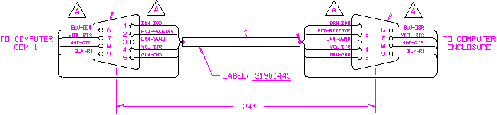
1. Pin 1 = Chassis Ground (Used For the Shield of the cable)
Pin 2 = Receive
Pin 3 = Send
Pin 4 = DTR (Data Terminal Ready)
Pin 5 = Ground (common)
Pin 6 = DSR (Data Send Ready)
Pin 7 = RTS (Ready To Send)
Pin 8 = CTS (Clear To Send)
2. DNC configuration suggestions are as follows.
A. The first suggestion to speed up the DNC down load is to turn text scrolling off. Either in your program as line 1 or as an MDI move, execute the following, M9243 X0. In manual mode you would press the number 6 key. This will bring up a screen that says M-function. You would then type in M9243 and press the Enter key. The X key will high-light and you press 0 and the Enter key. Press F10 key and energize the drives then press the green start button.
B. The next suggestion is sometimes depending on how many programs you have stored in the flash memory area you should lower the Buffer size. The following are the steps as to where to find the section on changing Buffer size.
1. Go to the setup utility screen.
2. Highlight Machine Installation and press the Enter key.
3. Using the down arrow key Highlight DNC Setup and press the Enter key.
4. If you do not have enough ram available lower to 16K.
5. Make sure line 1 which says Execution Mode is set for buffered not drip feed.
6. On the choice Ignore Tool Comp and Corner Radius leave the setting set to YES. If you choose no the down load will slow down as it has to check for these conditions before it ever cuts the part.
Chapter 7
Backing Up The Configuration File
Before Loading New Software
1. The following is suggested if you have a problem and need to reload older software to check out the problem. The following procedure illustrates the method to backing up your configuration file.
A. Go to the program page by pressing the F2 key.
B. Press the F8 key 3 times in a row.
C. Your cursor should now be sitting on ..\ Press the Enter Key while sitting on ..\ .
D. Using your down arrow key high-light the file name S11confi.cfg.
E. Press the F9 key (utility). Highlight Copy and press the Enter key.
F. Insert a blank formatted floppy into the ‘A’ drive.
G. Highlight ‘A’ and press the Enter key.
H. You have just backed up your configuration file. You should mark this disk with what version of software this matches with. Any time you install an updated version of software you should do the same thing using another backup disk, not the same backup disk that you just made.
L. Leave the disk in the ‘A’ drive, we are going to put a printable version of the same backup for you to read if necessary. After copy the configuration file to the ‘A’ drive press the F10 key multiple times until you get to the main menu which has the Setup Utilities showing on the screen.
M. Using the down arrow key Highlight Setup Utilities and press the Enter key.
N. Using the down arrow key Highlight General Software and press the Enter key.
O. Use the down arrow key Highlight Printer and press the Enter key.
P. Change Default Output Device from PRN to A:11config.txt
Q. Press the Enter key.
R. Press the F10 key a couple of times until the question comes on the screen “SAVE CHANGES” F1 = YES. Press the F1 key.
S. Go back into the Setup Utility screen again. Use the down arrow key and Highlight Print Configurations and press the Enter key. This is going to save a viewable backup of the configuration file. If you ever needed a hard copy you could take this disk to a computer which has a printer on it. Using an editor or just printing the file you could obtain a hard copy of your Setup Utilities.
Chapter 8
Common Error Messages
1. The following is a list of common error messages and what each means.
A. Subprogram Return Without A Call: In draw mode you setup a window of which blocks to run. You make a change and now do to the changes your subprogram is outside the specified runable area.
B. Subprogram Duplication Error: In a particular program you have 2 subprograms with the same name.
C. Not Enough Memory To Run: Based on the amount of programs you have stored on the flash memory board, the control ran out of memory space. The same can occur even if this is the only one program in memory. The control takes the existing program with a .m extension and converts it to a .s file. The .s file that is created can be as much as 2 times the original file size of the .m file. After adding the file size of the .m and the .s file the total has exceeded the available memory on the flash memory board.
D. Memory Exceeded: On some of the original systems this message will occur if you are running using cuttercomp. The problem occurs after you have run the part a couple of times. The fix for this problem is to check in your program and make sure the G40 statement has on the SAME LINE a ramp off either X or Y or XY move.
E. Circle Adjusted beyond Maximum adjustment: This usually occurs when you have created an arc off of a CadCam system. The arc is usually split in to two arc statements. The endpoint that is inputted shifts the center to allow the control to get to the programmed end point. This will usually cause an out of round condition on your part. The fix is to go into the Setup Utility
under General Software under Control software. Highlight circle adjustment generally it reads Adjust center. Change to Adjust Endpoint.
F. Can’t perform Check Disk on Drive (D): There is a file or directory that has gotten corrupted.
1. Put in the bootable Diagnostic disk and reboot the control.
2. Press the F1 key (run).
3. Press the F10 key (exit).
4. Press the F9 key.
5. Connect up an external key board. Type in the following: D: and press the enter key.
6. Insert a blank floppy disk into the ‘A’ drive.
7. Type copy S11confi.cfg a: and press the Enter key.
8. Type cd\user and press the Enter key.
9. Type copy *.m a: and press the Enter key. Hopefully the problem file is not one of the files you are attempting to backup. If it is you must backup each file one at a time until you have as many of them backed up that are not bad.
10. Next power down the 110VAC power. Remove the disk from the ‘A’ drive.
11. Open the door on the computer.
12. Remove the cover on the computer.
13. Remove the hold down bracket.
14. Find the board with the RED toggle switch. Remove this board. Note: Please follow the ESD instructions in chapter 3 section 5A.
15. Locate the battery which is near the bottom of the flash memory board. The
following drawing is the flash Memory board part number ![]() 31900496s.
31900496s.
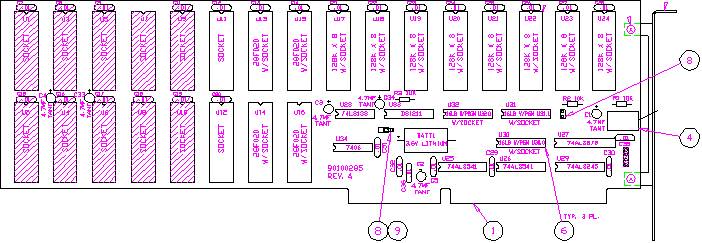
16. Just above the battery is a two pin jumper. On the drawing there is an arrow pointing to the jumper. The arrow is labeled 8 9 with a circle around each. This is in the middle of the board. Remove this jumper for about 2 minutes. This is going to erase memory and clear your problem.
17. Put the jumper back on after the 2 minute period and remount the board into the computer.
18. Put the circuit board retainer back on.
19. Put back on the cover to the computer and close the door.
20. Put your machine disk which is usually found in the programming manual into the ‘A’ drive.
21. Turn back on the computer and let the software boot.
22. Install the software answering the question as they show on the screen.
23. After the software has been reloaded, let the system reboot. Do not Attempt to run your system at this point! You must do the following first!!
A. After the system boots up go into CNC.
B. Press the F2 key (Program).
C. Put your disk that you backed up with the configuration file on it.
D. Press the F8 key (Display) 3 times in a row.
E. Highlight the top choice which looks like this ..\ and press the Enter key.
F. Press the F7 key (Log), You want to Highlight ‘A’ and press the Enter key.
G. Using the down arrow key Highlight the file S11confi.cfg.
H. Press the F9 key (Utility) and Highlight Copy.
I. Press the Enter key.
J. Highlight D and press the Enter key. This will copy the file S11confi.cfg to the root directory of ‘D’. Note the control should ask you “Do you want to overwrite the File” answer YES!
K. After this file has been copied remove the disk from the ‘A’ drive and reboot the system.
L. Check out the control and make sure everything works as normal.
M. If you want you could reinsert the disk which had the backup of your programs. You could copy these back to the user directory if you want to.
G. Cannot find Valid Security Device: On the motion board in the computer there is an IC that our system MUST see upon bootup.
1. Following the instructions in Chapter 3 section 5A. This section discusses the proper procedure on how to remove a board in our system. Of course make sure the power is off before you remove the motion board. Now just plug it right back in.
2. Turn the power back on and see if the same message returns. If it does you need to order a new motion board. Please look in Chapter 5 section 1. The Motion board drawings in order to determine which style board you have and which part number is associated with it.
H. M function Option not available: Check on the top of the computer there must be a key screwed into the connection labeled printer. This key could either be black in color or green in color.
1. If the key is plugged into the printer port then please check the following.
A. Is there a printer also connected to the key?
1. If there is a printer connected it MUST be turned on. If it is off it will not allow our software to read the key.
B. Go to CNC mode and press the F2 key (program).
1. Press the F9 key (utility).
2. Using the down arrow Highlight More and press the Enter key.
3. Using the down arrow Highlight System Info and press the Enter key.
4. At the top of the screen a serial number of the key should have appeared. Next to the serial number in square brackets is a 4 digit code. Please take note as to what this code is. If it is all zeros and there is no serial number, then the key is either blank or the printer cable is on backwards on the CPU board.
A. Did you have the key plugged into the printer port before the power was on? If you did not the problem is the control must read the key on power up. Reboot the control and check again repeating step B.
5. If the problem remains do the following:
A. Check the printer cable where it plugs into the CPU board. On the cable there is a single red line on the edge of the cable. This red line signifies pin 1. On the CPU board on the connector there is a pin labeled 1. Usually pin 1 is down but does not always have to be. Match pin 1 of the cable to pin 1 of the board of course making sure the power is off before unplugging anything. If the cable was wrong unplug correct the problem and check again. If the problem remains then most likely the key got erased when the cable was in backwards. You need to contact either your local Anilam Distributor with the color of the key that went bad or Anilam directly.
I. Simulation mode being forced on: If the drives did not come on correctly but the control detects the servos are on, and you command a move, this message will appear. Go to Chapter 4 Intermittent shut down section and follow the directions. After you think you found the answer to the problem do the following.
1. Go to the Setup Utility screen and press the Enter key.
2. Highlight Machine/Installation and press the Enter key.
3. Using the down arrow key Highlight the Miscellaneous choice and press the Enter key.
4. Using the down arrow key Highlight Force Simulation Mode and press the Enter key. You want to change this to NO. The password is Y10.
J. Construction Data base is full: This message occurs because you can only have 50 elements, which consists of line, points, or circles, in the Geometry Calculator section.
K. Lost (X or Y or Z) Feed back: This message means the control sent a signal out of the motion board but did not see any counts coming back in. Possible problems can be as follows.
1. No torque on the specified axis.
2. No counting on the specified axis.
3. No torque on all axis.
4. No counting on all axis.
Note: For above mentioned problems go either to the intermittent shut down chapter earlier in this manual or to the chapter on loosing zero.
L. Lag Over Max: This message can occur for the following reasons.
1. When your gibs are to tight causing a backlash type symptom.
2. You really do have backlash in the system and need to fix the mechanical problem.
3. If you turn on backlash compensation you must change the Servo Up Delay parameter, this parameter is located in the Miscellaneous section and Must be set to 3! The password is Y10. Also if the amount of backlash entered on any axis is larger then .0047 inches or .12 MM, you MUST go to the Position Error Check section in the Setup Utility screen. You must increase the choice Maximum Lag Error from .0047” to something a little larger then the maximum backlash you entered.
M. Distribution Board SOFT reset OK!: The control usually was busy doing some calculation when the distribution board sent a request to the computer to make sure the system was still running OK. Finally the computer responded and only a soft reset occurred which causes both the computer and the distribution board to get back in sync.
N. Distribution Board HARD reset OK!: This message is very similar to the previous message. The difference is the distribution board requested the CPU to reset everything. You can get the same message if you have a loose connection from the power supply that powers the distribution board. We have seen if you tap on this power supply the distribution board will reset. You will however shut down the servo when this message and problem occurs.
Note: On newer versions of software you might not see these messages any more. We have decided to disable the message even though the software is still sending the condition that would have made them appear. To enable the message do the following.
1. Be in manual mode with the key board.
2. Press the number 6 key (M code).
3. Type in the following M code M9241 Y1.
4. Press the F10 key.
5. Energize the servo drive and press the Start Button.
6. This will enable the messages to be displayed. To disable the messages Type M9241 Y0.
7. Energize the servo drive and press the Start Button.
O. Warning Cannot Reach Programmed Rapidrate: The following are some reasons that the system would display this warning message.
1. This can be cause by the rapid gain not being set properly.
2. The drive card is not setup properly.
A. Signal gain not set properly.
B. Tach adjustment not set properly.
C. Gibs to tight or mechanical problem.
D. Drive motor is undersized for machine.
Note: You can disable this warning. To disable the warning do the following.
1. Go into the Setup Utility screen.
2. Go to Machine/Installation and press the Enter key.
3. Go to Machine Axis and press the Enter Key.
4. Using the down arrow key Highlight Position Error Check and press the Enter key.
5. Highlight Error Checking and change from PEC & Rapid Warning to PEC only. Note: Do Not Turn PEC check OFF!!