Spindle axis setup info:
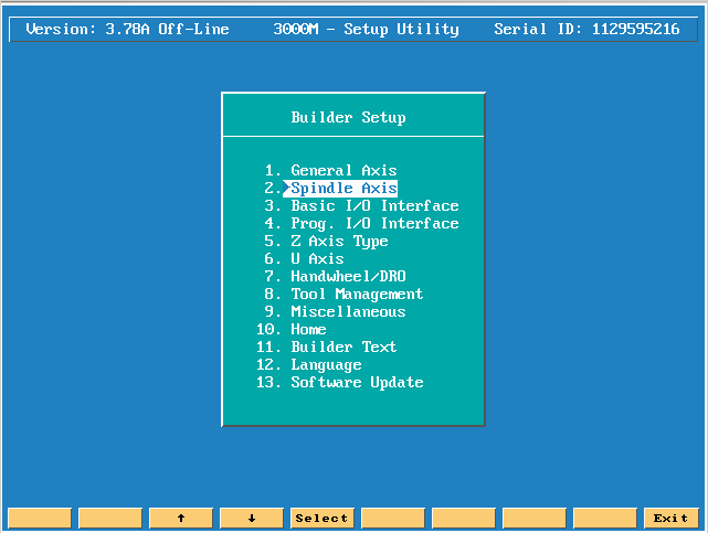
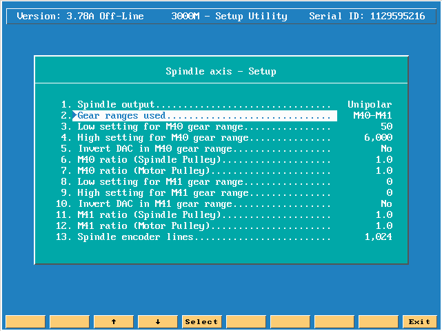
Press the Enter key on Spindle axis
Spindle output has 2 choices either Unipolar (0-10 volts DC output to spindle inverter) or Bipolar (-10 to +10 volts DC to spindle inverter).
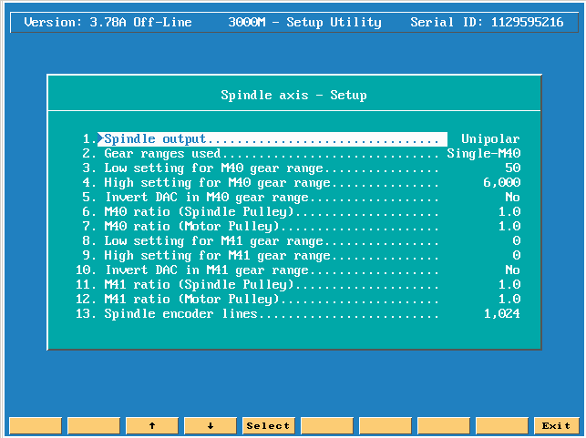

Gear ranges used has 2 choices either Single-M40 or M40-M41. Single M40 means there is only 1 spindle range from something like 50 – 5000 RPM.
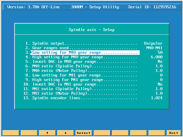
Next move down to Low setting for M40 gear range. On the legend of the spindle is usually printed the low and high values for each gear range. Enter in the proper low range value.
Next move down to High setting for M40 gear range. On the legend of the spindle is usually printed the low and high values for each gear range. Enter in the proper High range value.
The next choice only works if you have Bipolar Spindle output to allow us to Invert the DAC signal.
The next setting is M40 ratio (Spindle Pulley), if there is a ratio other then 1:1 you would then change this choice.
The next setting is M40 ratio (Motor Pulley), if there is a ratio other then 1:1 you would then change this choice.
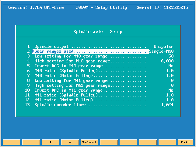
The second option is dual gear ranges.
M40-M41 means
there are 2 gear ranges based on a mechanical lever that you must change to go
in to low or what is call back gear. Note in order for our CNC to understand
this, a switch must be mounted so when either in the High range or Low range
the switch will be activated. The signal back to the CNC will tell us that we
are in either High or Low range based on the input setting in Basic I.O.
Interface, under the input functions screen. Click on link to jump to ![]() Basic I.O. Interface setup info.
Basic I.O. Interface setup info.
Next move down to Low setting for M40 gear range. On the legend of the spindle is usually printed the low and high values for each gear range. Enter in the proper low range value.
Next move down to High setting for M40 gear range. Enter in the proper High range value.
The next choice only works if you have Bipolar Spindle output to allow us to Invert the DAC signal.
The next setting is M40 ratio (Spindle Pulley), if there is a ratio other then 1:1 you would then change this choice.
The next setting is M40 ratio (Motor Pulley), if there is a ratio other then 1:1 you would then change this choice.
Next move down to Low setting for M41 gear range. Enter in the proper Low range value.
Next move down to High setting for M41 gear range. Enter in the proper High range value.
The next choice only works if you have Bipolar Spindle output to allow us to Invert the DAC signal.

Next move down to M41 ratio (Spindle Pulley), if there is a ratio other then 1:1 you would then change this choice.
Next move down to M41 ratio (Motor Pulley), if there is a ratio other then 1:1 you would then change this choice.
The next choice is Spindle encoder lines. If you actually have an encoder mounted on the spindle to give the true RPM the spindle is running, you must tell the CNC what the line count of this encoder is, otherwise you don’t need to change this if you don’t have an encoder!
The next choice goes hand in hand with the previous entry. If you have an encoder mounted on the spindle then you choose Feedback as your Spindle RPM Display!
If you don’t have an encoder mounted on the spindle then you choose Display as your Spindle RPM Display!

The next choice wants to know if you want the Spindle to start and stop when the Hold or start keys are pressed.
The next entry Stop program and Spindle on gear range error, either yes or no.
The next entry is related to the earlier question regarding an encoder for the spindle speeds. If there was an encoder to track the true RPM, is it mounted directly to the motor, Yes or no are your choices.
The next entry wants to know at what RPM do you want the CNC to consider the spindle has gotten to Zero speed from 10 RPM or less?
The next entry wants to know at what RPM do you want the CNC to consider the spindle has gotten to speed 95% of programmed speed?