Handwheel/DRO setup info:
Press the enter key on Handwheel/DRO

Press the enter key on Handwheel/DRO #1.

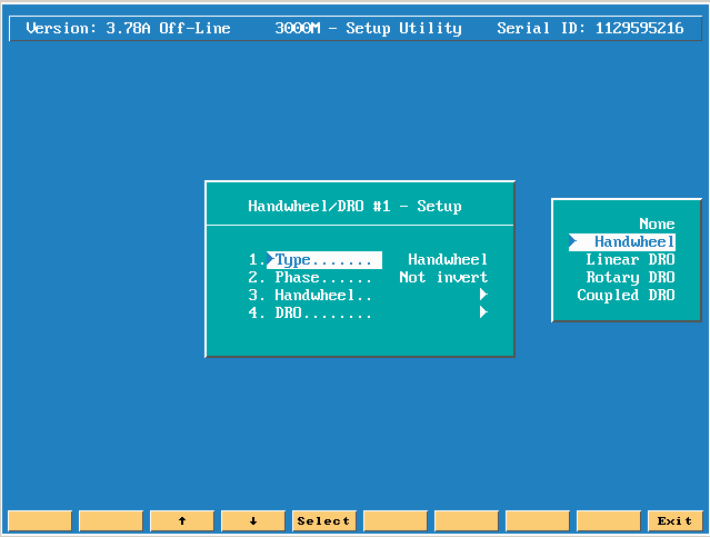
Press the enter key on TYPE to see your choices.

The following are your possible choices:
None, this option is not being used.
Handwheel, you could have an electronic handwheel plugged in to DRO #1 wiring harness.
Linear DRO, you could have a Linear scale connected to display motion for instance on the Knee.
Rotary DRO, you could have a Rotary manual table connected.
Coupled DRO, if you had a scale mounted to the knee you can couple the Knee and Z axis so when either is moved the Z axis display will show the correct position of your part.
Note: If you use coupled DRO you must also put a coupled tolerance in on the previous screen.
Please note: if you are either using coupling to reset the DRO screen you must do the following:
There is an M code 9247 that must be used!
Press # 6 key (mcode) type in 9247 and press the enter key.
In the X display type in either 0 or 1, (0 = DRO port 0, which on our screen says DRO #1), or (1 = DRO port #1, which on our screen says DRO #2).
In the Y display put in 0 if you want to zero the DRO display amount, but if the Z axis has also been moved then you would press the Z key and then the enter key to completely 0 the Z axis display!

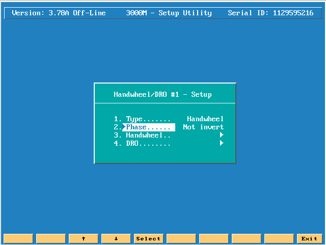
The next choice down is phase, if the axis is counting backwards then you can either invert or not invert the encoder phase.

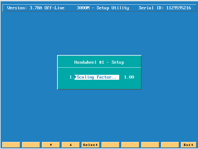
Press enter on handwheel.

This choice wants to know if the electronic hand wheel is 1:1 scaling factor.
The next entry is related to the DRO possibilities.

If you press the enter key on Display Axis a menu of options will appear.
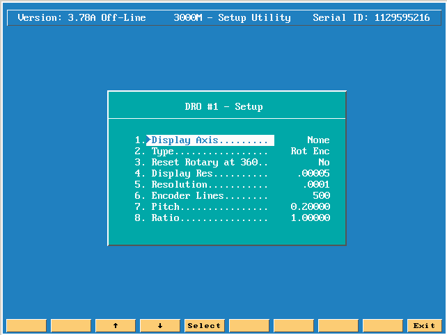
You can either choose None, or you can have U, V, or W appear on the CNC screen as a DRO axis.
Please note: if you are either using coupling or just a DRO mode, to reset the DRO screen you must do the following:
There is an M code 9247 that must be used!
Press # 6 key (mcode) type in 9247 and press the enter key.
In the X display type in either 0 or 1, (0 = DRO port 0, which on our screen says DRO #1), or (1 = DRO port #1, which on our screen says DRO #2).
In the Y display put in 0 if you want to zero the DRO display.

The next choice is Type. Press the enter key on TYPE your choices are Linear or Rotary.


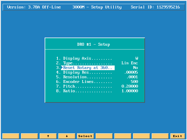
The next line down wants to know if you want to reset back to 0 when you reach 360 degrees Yes or No.

The next line down is the Display Resolution choice.

You pick from the menu what the display resolution should be. You can only choose a resolution that is equal to, or less then, the Resolution line amount, the next entry down!

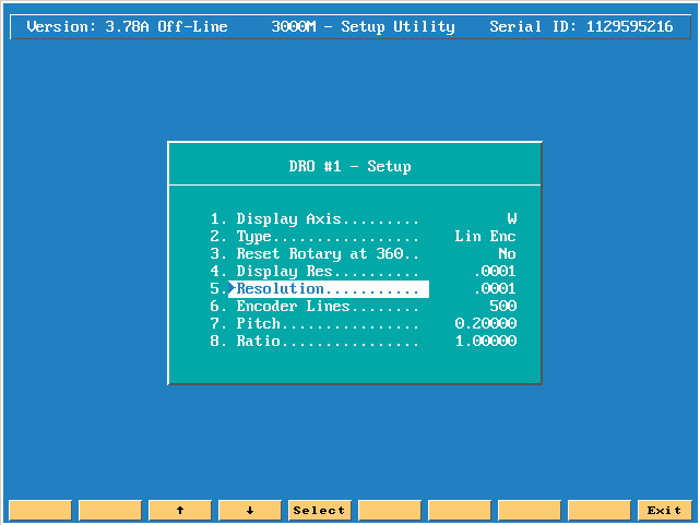
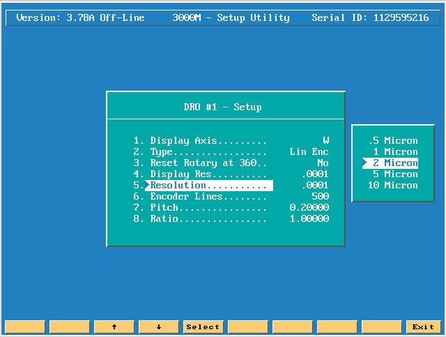
The next line down Resolution is the actual resolution of the axis. Press the enter key to see the option menu of resolutions.
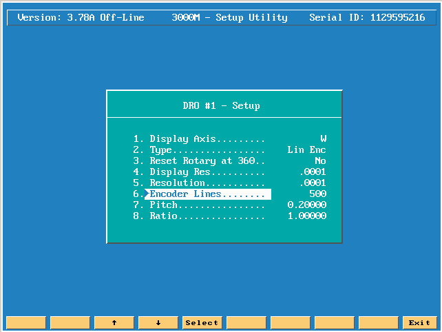
The next line down Encoder lines is used when you are using a rotary encoder. You enter the exact line count for the encoder being used.
The next line is Pitch, if there is a pitch amount related to this DRO axis, you would then enter in what ever the proper pitch is.

The last line is Ratio.

If you press F10 (EXIT) 1 time you have the same exact options for Handwheel./DRO #2.

The next line down Coupled Tolerance must have a value if in either DRO #1 or DRO #2 you have chosen Coupled DRO!
The amount you enter is based on the parts you are making. If the coupled axis happens to move up or down a little bit, how far will you allow this to move before we abort and give a message like Coupled Tolerance exceeded message on the CNC screen while an axis is cutting.