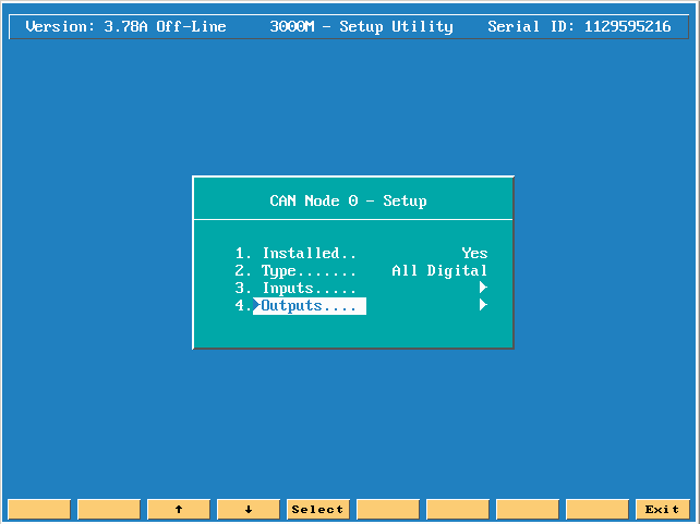
Can Node 0 Outputs setup info:
Move down to outputs and press the enter key to see the next menu.
The CNC can generate up to 98 M-functions (M1 to M98) and an Auto/Manual output. An M-function can activate or deactivate the ports
assigned to it. A port can be assigned to more than one M-function. To assign an output port to an M-Function:
1. See Map 9, I/O Nodes Setup, Menu D in manual ![]() 70000499F.
70000499F.
2. Highlight CAN Node 0 or CAN Node 1 to activate Menu E.
3. In Menu E, highlight Outputs, and press ENTER. Use this menu to configure M-functions as follows:
From Menu I, highlight the M-function to be configured, and press ENTER.
Menu J activates. Highlight Unused, Bit On, or Bit Off; or press ATTR (F7).
Menu K activates. Highlight a bit from 0 to 5, and press ENTER.
Menu M activates. Use Menu M to configure the following parameters:
Pulse(msec) Port output is maintained for the period specified in milliseconds by the builder. Any value from 0 to 32,000 is allowed. If a zero (msec)
pulse is used, output is maintained until port is turned off. The CNC will delay run of the program for the duration of a nonzero (msec) Pulse.
Delay(msec) Holds program run for the specified period of time after completion of the M-function. Type the number of milliseconds.
Any value from 0 to 32,000 is allowed. If the Delay(msec) is set to zero, there is no delay.
The following is what a standard system with m-functions should look like!
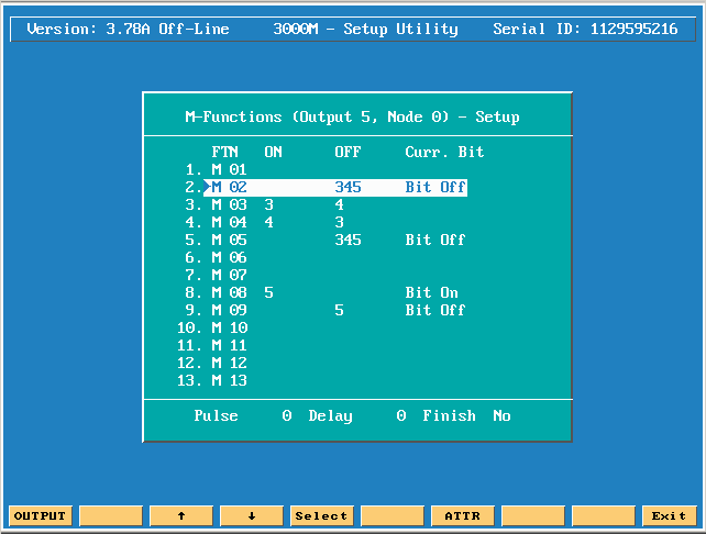
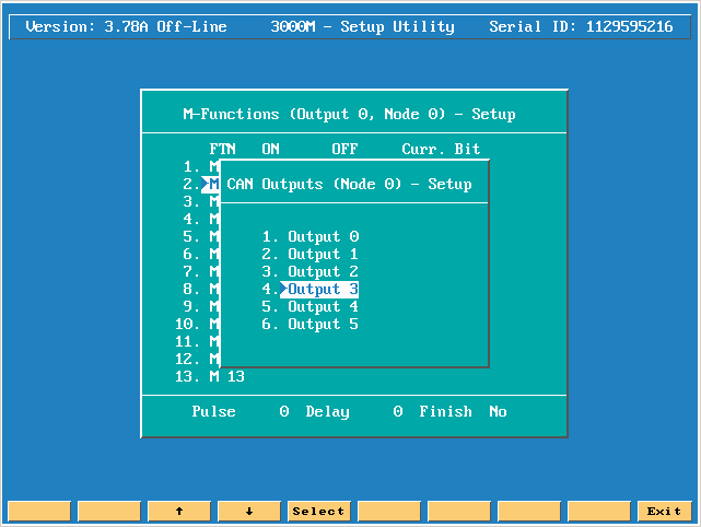
To achieve this do the following: Move down to M02 and then press F1 (OUTPUT) key and move down to OUTPUT 3 and press the enter key.
Press the enter key and select Bit OFF and press the enter key
Move down to M3 and press the enter key and turn Bit ON.
Move down to M4 and press the enter key and turn Bit OFF.
Move down to M5 and press the enter key and turn Bit OFF.
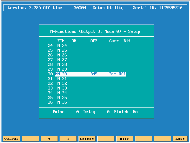
Move down to M30 and press the enter key and turn Bit OFF.
Press F1 (OUTPUT) and move down to OUTPUT 4 and press the enter key.
Press the enter key and turn Bit OFF.
Move up to M5 and press the enter key and turn Bit OFF.
Move up to M4 and press the enter key and turn Bit ON.
Move up to M3 and press the enter key and turn Bit OFF.
Move up to M2 and press the enter key and turn Bit OFF.
Press F1 (OUTPUT) and move down to OUTPUT 5 and press the enter key.
Press the enter key and turn Bit OFF.
Move down to M5 and press the enter key and turn Bit OFF.
Move down to M8 and press the enter key and turn Bit ON.
Move down to M9 and press the enter key and turn Bit OFF.
Move down to M30 and press the enter key and turn Bit OFF.
Your screen should now look like the picture below.
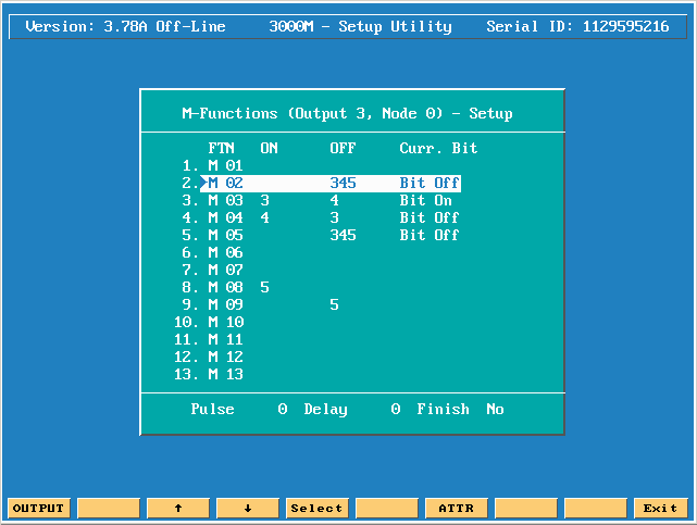
M30 should look like the picture below .
As mentioned earlier you can also change the attributes of the output bit. Let us say you are connecting up an indexer, the following would be what you would need to do.
Press F7 (ATTR) key to get to the ATTRIBUTES screen.
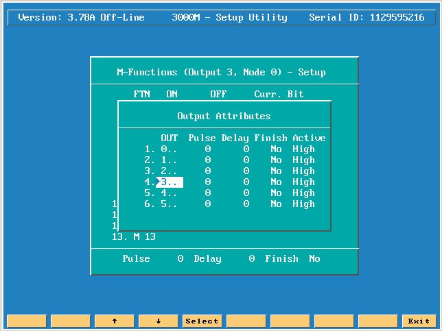
Press the enter key to see the next menu.
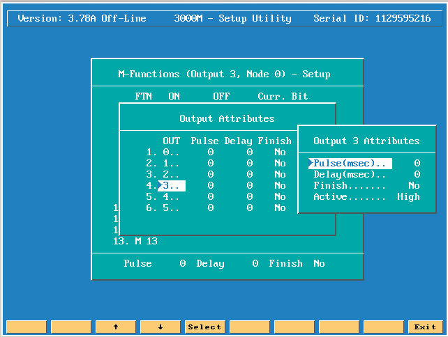
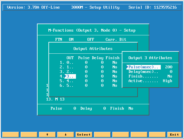
Press the enter key on PULSE and type in 200 and press the enter key.
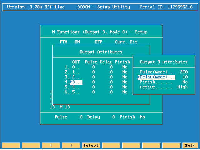
If you want the output to wait for finish then move down to Finish and press the enter key to change to YES.
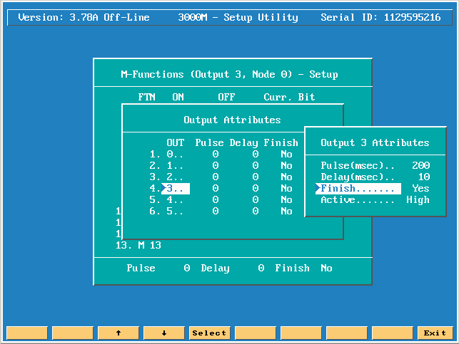
If you are using Feed Hold Input through the forward and reverse relays then you need to highlight Delay and put in like 10 ms.
After you have set all of your Attributes this is what the screen should look like.
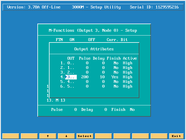
Please note the above attribute example was done using output bit 3 which is Spindle forward normally! Typically you would choose one of the available output bits on the P3 connector pins 11 – 16. Spindle forward is usually on connection P3-14 or look at P13 connector and if this harness is plugged in, then it is connected under the servo control board and you won’t see the connections back to P3–14!
Abetter example would be to use bit 0 which normally is not connected to anything!