Servo Won’t Energize
1. Is the Spindle Auto/Manual switch in auto?
2.
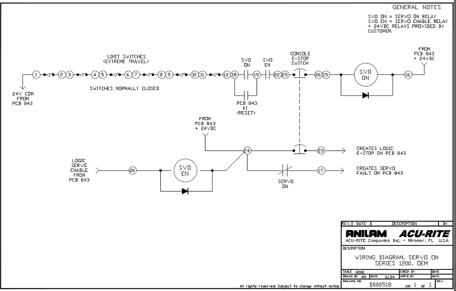
The following drawing is the servo ![]() turn on circuit:
turn on circuit:
3. Reboot the computer and check the messages. The following message is what you should see. M 2 Motion Brd + D 2 Distrib. Detected.
Note: you might also see M1, M2, M4 or M5 and either D1, D2, or D3 Distrib boards detected.
A. Do you have this message?
1. If no, did the message say M 2 Motion Brd + Non Distrib. system Detected. If
this is the message go to ![]() lost sync and follow instructions there.
lost sync and follow instructions there.
2. If you had the correct original message then open the servo box door and check on the distribution board front left hand corner LED’s L7, L8, L9, and L12, must be illuminated. If any of these are out check the limit switch that corresponds to the LED. L7 usually is the X limit switch, L8 usually is the Y axis limit switch, and L9 usually is the Z axis limit switch. If X axis is the problem then all 4 LED’s will be off. However please check the 4 LED’s on the back left corner of the distribution board labeled L1, L2, L3, and L4, these must be illuminated !
The
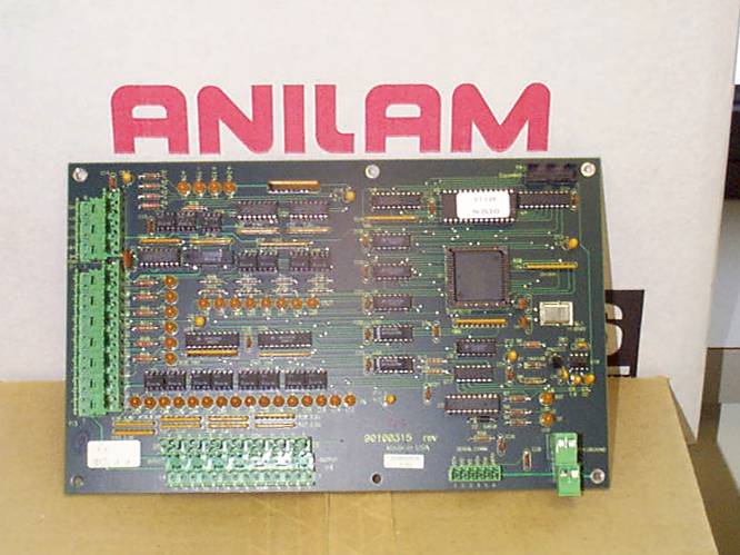
distribution Board part # ![]() 31900886S.
31900886S.
4. Is the 24VDC LED labeled L4 illuminated? If yes go to ![]() step 5. Otherwise continue.
step 5. Otherwise continue.
A. If the answer is no, please check the Pc 801 board. On this board there is a
1 amp fuse (F1) which controls the 24VDC output. If the fuse is OK please check
for the 24VDC right on the 24 volt power supply that is plugged into to PC 801
board P5 connector. Check across the Yellow and Blue colored wires. If you do
not have any voltage please unplug the F1 fuse located on the PC 801 board and
recheck. If the voltage comes back then there is an external short causing the
voltage to drop away move to ![]() step
B in this section otherwise continue with the next step.
step
B in this section otherwise continue with the next step.
1. If the voltage did not come back please check the black and white wire
across the transformer of the 24 volt supply. You should see 110 VAC across
these two points. If you have 110 VAC then your power supply is bad order part
# ![]() 31500190s
from your local Anilam distributor or from Anilam directly.
31500190s
from your local Anilam distributor or from Anilam directly.
2. If the 110 VAC was not there please check the white 15 amp slo-blo fuse
located on the PC 801 board; it is labeled F2. There should be 110 VAC Hot on
both sides of the fuse in reference to TB1-1. If you have no voltage on either
side of the fuse check TB1-1 and TB1-2 for 110 VAC. If you have the voltage at
these points you have blown a trace on the PC 801 board. Please either repair
the wire trace or order a new PC 801 board. The part # is ![]() 31500321s or
31500321s or ![]() 31501002s
PC 811 PCB.
31501002s
PC 811 PCB.
3. If there is no voltage at TB1-1 to TB1-2, please check the terminal strip that is located above the PC 801 board across the terminals labeled 0 and 110. There should be 110 VAC across those to points. If the voltage isn’t there then it has to be a wiring connection problem on the terminal strip jumping the voltage from one contact point to the next point. Please repair as necessary and recheck if everything now works correctly. If everything works do not go to step B.
![]() B. If the voltage came back after removing the F1 fuse go to
the distribution board and remove the P4 plug. Replace the fuse and recheck. If
the voltage is still there the short is caused by something wired to the P4
cable. Check for shorts in the cable and check for shorting to ground in the same
cable. If the problem persists please contact your local Anilam distributor or
Anilam directly.
B. If the voltage came back after removing the F1 fuse go to
the distribution board and remove the P4 plug. Replace the fuse and recheck. If
the voltage is still there the short is caused by something wired to the P4
cable. Check for shorts in the cable and check for shorting to ground in the same
cable. If the problem persists please contact your local Anilam distributor or
Anilam directly.
![]() 5. At this point you should have L1, L2, L3, L4, L7, L8,
L9, and L12 LED’s illuminated ! If all of these are on but the servo still will
not energize please check the voltage from the PC 801 board connections TB1-4
and TB1-5 for 110 VAC after you press the reset button. If you have the 110 VAC
across the terminals TB1-4 and TB1-5 follow the wires to the fuse or fuses and
see if you have 110 VAC on both sides of the fuses. Next check the large
blue capacitor, see if you have 160 VDC across the 2 screws on top of the
capacitor. If you do not have the voltage you have a bad bridge rectifier part
#
5. At this point you should have L1, L2, L3, L4, L7, L8,
L9, and L12 LED’s illuminated ! If all of these are on but the servo still will
not energize please check the voltage from the PC 801 board connections TB1-4
and TB1-5 for 110 VAC after you press the reset button. If you have the 110 VAC
across the terminals TB1-4 and TB1-5 follow the wires to the fuse or fuses and
see if you have 110 VAC on both sides of the fuses. Next check the large
blue capacitor, see if you have 160 VDC across the 2 screws on top of the
capacitor. If you do not have the voltage you have a bad bridge rectifier part
# ![]() 90500605
or a broken wire or bad crimp.
90500605
or a broken wire or bad crimp.
A. If the 160 VDC across 2 screws on the capacitor is present, look at the drive cards. On the drive card there is a small RED Fault light. Is the fault light on?
1. If the light is on, is it illuminated on all of the drive cards?
A. If at least 1 drive card fault light is off, then this one axis should be OK. Try moving each drive board into the one good axis and energize the drives again. Does the LED on this board illuminate and stay on or does it go back out?
1. If it stays on this drive card is bad. You need to order a new one. If
this drive card says ANILAM on the sticker of the drive card itself Anilam’s
part # is ![]() 31500966s.
Keep checking all axis the same way until we know how many drive cards are
working. If the drive card does not say Anilam then you must contact the
machine manufacturer or the distributor that sold you the equipment. This drive
card is not an Anilam part.
31500966s.
Keep checking all axis the same way until we know how many drive cards are
working. If the drive card does not say Anilam then you must contact the
machine manufacturer or the distributor that sold you the equipment. This drive
card is not an Anilam part.
2. If the light went out then you should be able to move the axis that this board is plugged into. If you can move the axis back and forth, then the card is OK, we need to check all the boards the same way.
A. We want to next check the motor cable that is screwed into the servo box for the axis that caused the fault lights to come on. We need to check for any shorts to the casing of the motor. We also need to check for any shorts in the cable to any other wires in the cable. If you find what seems to be a short in a cable unscrew the other end from the motor and recheck the same way.
1. Did the short go away? If yes, then check the motor. If no, then check the 1 good cable the same way and compare results. All axis should have the same characteristics in the motor and motor cable wiring. Once we have found the bad item that will either be the motor or the motor cable or both, continue checking the remaining axis the same way.
2. Once we know what items are good, or at least do not have any shorts, take your good drive card and put it in the axis that wasn’t working and energize the drive. Did the fault light come on and go back off? If yes, can you move the axis in both directions? If you can great! Check all axis the same way. Once you have determined what items caused the problem please contact your local Anilam distributor or Anilam directly to get the replacement parts.
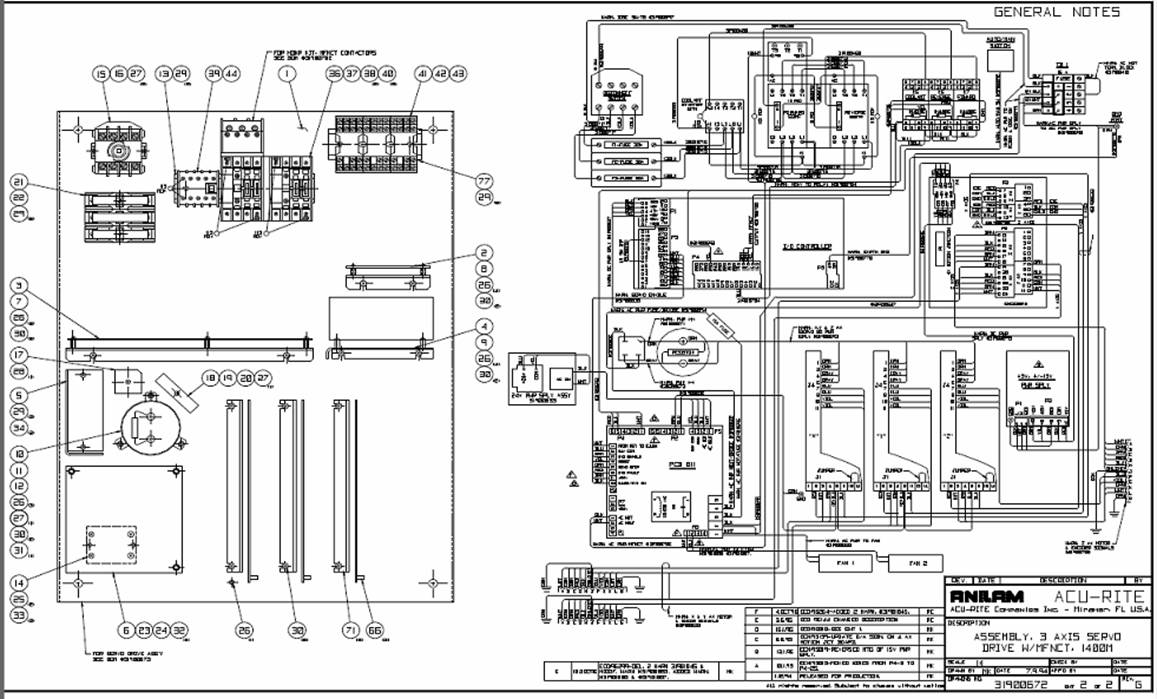
![]() This drawing is the overall wiring diagram for a Double box
system 1400:
This drawing is the overall wiring diagram for a Double box
system 1400: