Rigid Tapping Filter setup info:
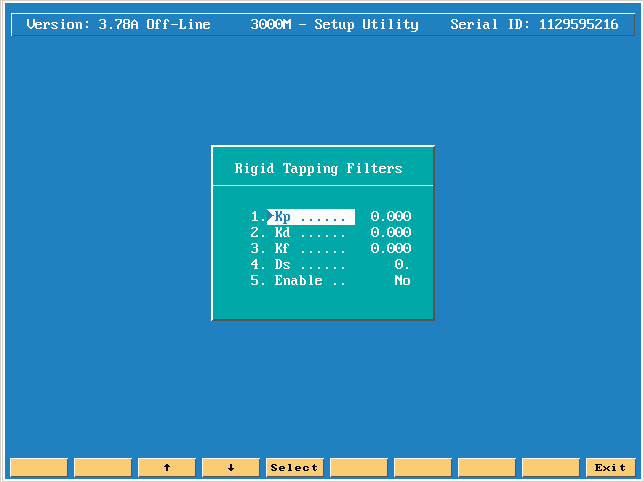
Press the enter key on Rigid Tapping Filters.

Note: in the
Motion setup testing manual part # ![]() 70000635B. Click on link and go to page 30 for
more information!
70000635B. Click on link and go to page 30 for
more information!
These parameters enable tuning customized to the output of the combination of servos, motors, and feedback devices on a specific installation.
These setup menus allow the operator to set a higher gain value for Feed moves, which require greater accuracy than Rapid moves. In Rapid Mode, machine inertia, available servo drive output power, and other mechanical factors must be considered. The No Motion gain values control the gain of the axes when the machine is holding position. An understanding of motion control theory is required to change these values properly.
When the CNC commands a move, the output from the system is a digital word representation of that move. The CNC derives this digital word from the output of the interpolators, which creates a move-required value that it feeds to the Digital Proportional, Integral, and Derivative Gain (PID) Filter, so that the following equation can define the output [digital word]:
Output = Voltage Offset + (Kp + Ki + Kd)
Refer
to ![]() Table
2-3, System Output Values and Definitions for a detailed
explanation of parameters.
Table
2-3, System Output Values and Definitions for a detailed
explanation of parameters.
![]() Table 2-3, System Output Values and Definitions
Table 2-3, System Output Values and Definitions
|
Value |
Definition |
|
Voltage offset |
A fixed voltage value always present at the output. |
|
Kp + Ki + Kd |
The Digital PID Filter Parameters. |
|
Kp |
Proportional Gain. This value is derived by directly multiplying the Kp coefficient by the position error. It is designed to compensate for immediate changes in servo error position. |
|
Ki |
Integral Gain. This value applies a long-term accumulation of error correction over time. It is used to ensure that the static position error is zero: 0 position error at rest or at constant velocity. It is derived by multiplying the Ki coefficient by the position error and then adding it to the previously computed Integral Gain value. |
|
Kd |
Derivative Gain. This value reacts to a change in error over time. The Derivative value is calculated by multiplying the Kd coefficient by the current error minus the error calculated in the previous sample. |
|
Kf |
Feedforward Gain. Feedforward gain is used to reduce the amount of lag (following error) that an axis generates during constant velocity. |
|
IL |
Integral Limit. The total maximum amount of Ki correction permitted by the Digital Filter. Ki gain effect is held to a preset maximum (the IL term), which is the total maximum amount of Ki correction permitted by the Digital Filter. |
|
Ds |
Derivative Sampling Time. The rate at which the derivative gain (Kd) is applied. |