1100 Signal adjustment procedure
Step 1. For an M2 motion board system.
1) Turn off the 110 VAC to the control
2) For a double box system
continue, for a single box system M3 motion board go to ![]() step 2.
step 2.
3) Open the door to the servo box and the door to the computer and remove the cover on the computer.
4) Turn on the 110 VAC power and turn back on the 3 phase disconnect switch, take a crescent wrench and rotate the shaft clockwise about a ¼ turn until the disconnect switch is on.
5) 
6) Boot up to the software options screen. You have two possible options, either Diagnostics or Motion Setup and Testing.
7) If you have the
Diagnostics choice continue but if you see Motion Setup and Testing go to ![]() step 3.
step 3.
8) For Diagnostic setup you will need to get your Diagnostic disk and put it in to the floppy drive and then select Diagnostics from the menu and follow the directions on the screen to boot on the disk.
9) If you don’t have a
diagnostic disk and need to make one click on this link ![]() DIAGNOSTIC
DISK and then follow the directions on the screen.
DIAGNOSTIC
DISK and then follow the directions on the screen.
10) After the disk has been created then do the following: put this disk into the floppy drive and then select Diagnostics from the menu and follow the directions on the screen to boot on the disk.
11) Press the F1 key (RUN) diagnostics.
12)

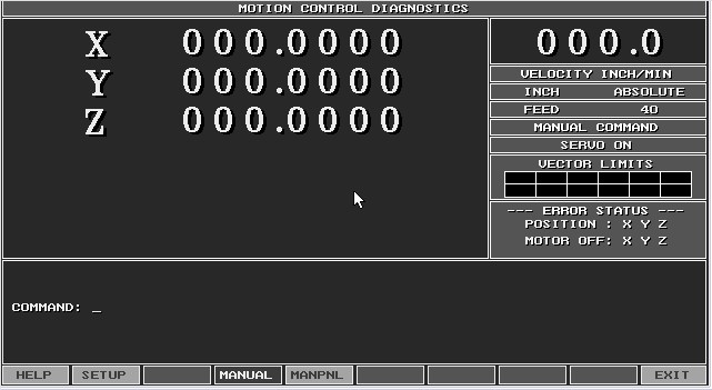
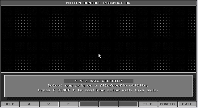
13) After the screen comes up move over to MOTION and press the Enter key.
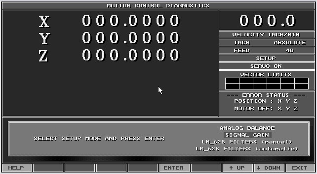
14) Press F2 (SETUP)
15) Select Signal Gain and press the Enter key.
16) 
17) Press F2 (X) and then press the START button.
18)

19) Look at the screen below, there is a box on the bottom right corner on the screen which has just appeared. The top digits 000.0 represents the feed rate. This feed rate must be 10 % of the fastest axis speed. For a 200 inch rapid system this number must be 20.0 to 20.5. If the value is not 10% of the rapid speed then on the drive board there is a potentiometer labeled SIG. Adjust the SIG pot to achieve the proper value!
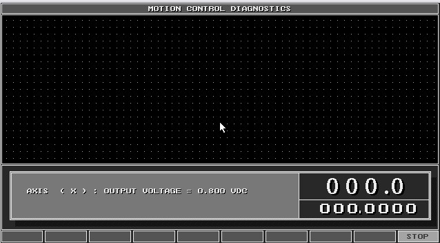
20) Look at the drive board part # 31500966S figure 1 for the SIG potentiometer.

21) Press the F3 (Y) axis button and press the START key.
22) 
23) Repeat steps 19 and 20.
24) After Y axis is adjusted to 10% of the fastest axis. Press the F4 (Z) axis button and press the START key.
25) 
26) Repeat steps 19 and 20.
27) After Z axis is adjusted to 10% of the fastest axis. Press in the Emergency stop button.
28) Press the F10 (EXIT) key multiple times, you are done with the Signal Gain procedure you may exit the Diagnostic software.
Step 2. For single box system with M3 motion board do the following:
1) Open the servo box door.
2) Remove the cover from the computer.
3) There usually is a bypass switch mounted on the edge of the servo box. Gently pull on the shaft so the switch will lock into the out position.
4) Put in the diagnostic disk into Drive A, and turn on the 110 VAC power. Select Diagnostics from the menu and follow the directions on the screen to boot on the disk.
5) If you don’t have a
diagnostic disk and need to make one click on this link ![]() DIAGNOSTIC
DISK and then follow the directions on the screen.
DIAGNOSTIC
DISK and then follow the directions on the screen.
6) After the disk has been created then do the following: put this disk into the floppy drive and then select Diagnostics from the menu and follow the directions on the screen to boot on the disk.
7) Press the F1 key (RUN) diagnostics.
8)
9) After the screen comes up move over to MOTION and press the Enter key.
10) Press F2 (SETUP)
11) Select Signal Gain and press the Enter key.
12)
13) Press F2 (X) and then press the START button.
14)
15) Look at the screen below, there is a box on the bottom right corner on the screen which has just appeared. The top digits 000.0 represents the feed rate. This feed rate must be 10 % of the fastest axis speed. For a 200 inch rapid system this number must be 20.0 to 20.5. If the value is not 10% of the rapid speed then on the drive board there is a potentiometer labeled SIG. Adjust the SIG pot to achieve the proper value!
16) Look at the drive board part # 31500966S figure 1 for the SIG potentiometer.
Figure 1
17) Press the F3 (Y) axis button and press the START key.
18)
19) Repeat steps 19 and 20.
20) After Y axis is adjusted to 10% of the fastest axis. Press in the Emergency stop button.
21) Press the F10 (EXIT) key multiple times, you are done with the Signal Gain procedure you may exit the Diagnostic software.
Step 3. For either the M4 or M5 motion board testing do the following:
1) Move down to the Motion Setup and Testing screen and press the Enter key.
2) Turn on your servos, pull out the Emergency stop button and press the Reset button.
3) Press the X key on the main CNC key board. In the top left hand corner it must say active axis X.
4) Next press the F7 (Signal Gain) key.
5) Type in the password Y10 and press the Enter key.
6) Press the number 2 key (in place of the 0 in the TSEC value)
7) Press the Start key.
8) On the screen you should see X
Y
Z
F
9) The value in the F screen is the feed rate which must be 10 % of the fastest axis speed. For a 200 inch rapid system this number must be 20.0 to 20.5. If the value is not 10% of the rapid speed then on the drive board there is a potentiometer labeled SIG. Adjust the SIG pot to achieve the proper value!
Look at the drive board part # 31500966S figure 1.
Figure 1
10) After the X axis has been adjusted to 10 % of the fastest axes, press the F4 (Manual) key.
11) Press the Y key on the main key board. In the top left corner it must say active axis Y!
12) Repeat steps 4 – 9.
13) After the Y axis has been adjusted to 10 % of the fastest axes, press the F4 (Manual) key.
14) Press the Z key on the main key board. In the top left corner it must say active axis Z!
15) Repeat steps 4 – 9.
16) After all 3 axes have been adjusted to 10% of the fastest axis, push in the Emergency stop button. You have completed this procedure. Press the F10 (EXIT) key try running the machine as normal and see if everything is running and working correctly.