Crusader Balance Procedure:
Step 1. You need to identify which style servo box you have
![]() Westamp drive board 31500080 replaced by
Westamp drive board 31500080 replaced by ![]() 31501005S
Qty 2, and 1
31501005S
Qty 2, and 1 ![]() 31501009S, has 3 amp plugs on the
board 1 at the top and two on the front edge. Click on part # 31501005S and
31501009S to see current style drive board.
31501009S, has 3 amp plugs on the
board 1 at the top and two on the front edge. Click on part # 31501005S and
31501009S to see current style drive board.
Note: Westamp, Servo Dynamics, Torque Systems, Fenner, or the Current style Glentek drive card are all adjusted the same!
Step 2. For either type system do the following:
Turn off the 110 vac to the system.
Flip open the top console, mark your scale cables for X, Z, and Spindle axis and remove them from the back of the console.
You want to locate the D/A board which is the board closest to the front with red ejector tabs. On this board there are pairs of potentiometers, you should notice that of each pair one of the pair has some red sealing substance, do not break the seal! When looking from the front view at this board the potentiometer on the left side is X axis, the middle one is Z axis and the far right one is the Spindle axis adjustment.
Step 3. If you have the WESTAMP type system
with the PC 803 board go to ![]() step 4.
step 4.
If you have the WESTAMP type system with a terminal strip, walk around behind the cabinet and open the servo box door.
Take out your digital voltmeter and put it on DC millivolts. Turn on the 110 to the control and then pull out the red E-Stop switch on the console and press the reset button. The servo motors should now have power on them and you might notice the ballscrews for each axis are slowly turning, this is normal. Take your voltmeter and touch on the terminal strip across A and B you are looking for zero. If you have anything other then zero go up in to the console to the X axis potentiometer and adjust it until you get to zero. Once terminals A and B are set to 0, move your leads to pins C and D on the bottom of the same drive board. Once again we are looking for 0 volts D.C. If you don’t have 0 on your meter then look at the front edge of the board, you will see 2 potentiometers. One of the potentiometers is labeled BAL (Balance). Turn this until you get 0 on your meter. If you have done both of these steps correctly that axis handwheel will no longer be turning!
Repeat step 3 for the other 2 axis. The drive cards are usually labeled X on the left, Y in the middle, and Z axis on the right.
Note: once you have completed this step, you do need to do the signal gain test next.
Step 4. If you have a WESTAMP style drive board we need to determine how the console cable to the servo box is connected to the servo cabinet.
The second style
had a pc 803 board to connect to see print # ![]() 30100149
go to
30100149
go to ![]() step 5.
step 5.
The first
style servo cabinet used a terminal strip see the following print # ![]() 30100134 continue
with step 4.
30100134 continue
with step 4.
If you have the 1st style a terminal strip system, A and B is the X axis signal, C and D are the Y axis signals, and E and F are the Z axis signals from the console.
Open the servo box door.
Take out your digital voltmeter and put it on DC millivolts. Turn on the 110 to the control and then pull out the red E-Stop switch on the console and press the reset button. The servo motors should now have power on them and you might notice the handwheels on each axis are slowly turning, this is normal.
Take your
voltmeter and touch on the terminal strip connections A and B you are looking
for zero. If you have anything other then zero go up in to the console to the X
axis potentiometer and adjust it until you get to zero. Repeat the same steps
checking C and D, and E and F and adjusting the proper potentiometer in the
console see ![]() Figure 2 for potentiometer
information.
Figure 2 for potentiometer
information.
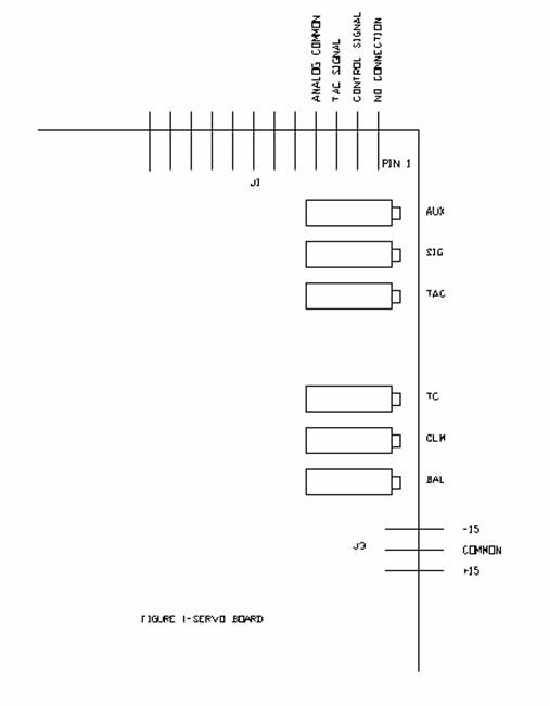
1) Next on the top edge of the Westamp drive card there is a connector labeled J1.
Press the Emergency Stop. Move the meter leads to pin 3 and 4 of connector J1 of servo board for X
axis.
See ![]() Figure
1.
Figure
1.
2) Pull out E-Stop and reset the servo. Meter should read 0
millivolts. If it does not adjust BAL potentiometer on X axis servo board
until it reads 0 Millivolts. See ![]() Figure 1.
Note: If the axis is moving slowly at this point, reading will be
something other than 0. If there is movement and a 0 reading check meter
connection and setting.
Figure 1.
Note: If the axis is moving slowly at this point, reading will be
something other than 0. If there is movement and a 0 reading check meter
connection and setting.
3) Repeat step 4-1 for the other 2 axis.
Note: once you have completed this step, you do need to do the signal gain test next.
Step 5. The Westamp style using pc 803 board part # ![]() 31500328,
and wiring diagram #
31500328,
and wiring diagram # ![]() 30100149
adjusts as follows:
30100149
adjusts as follows:
1) Open the servo box door.
Take out your digital voltmeter and put it on DC millivolts. Turn on the 110 to the control and then pull out the red E-Stop switch on the console and press the reset button. The servo motors should now have power on them and you might notice the handwheels on each axis are slowly turning, this is normal.
Take your
voltmeter and touch on the PC 803 board part # ![]() 31500328,
the P8 connector (Pin 1 is closet to the edge of the board). P8 Pins 1 and 2 =
X, pins 3 and 4 = Y, and pins 5 and 6 = Z axis signal from the console you are
looking for zero. If you have anything other then zero go up in to the console
to the X axis potentiometer and adjust it until you get to zero see
31500328,
the P8 connector (Pin 1 is closet to the edge of the board). P8 Pins 1 and 2 =
X, pins 3 and 4 = Y, and pins 5 and 6 = Z axis signal from the console you are
looking for zero. If you have anything other then zero go up in to the console
to the X axis potentiometer and adjust it until you get to zero see ![]() Figure 2.
Repeat the same steps checking pins 3 and 4, and pins 5 and 6 and adjusting the
other 2 axis to achieve 0.
Figure 2.
Repeat the same steps checking pins 3 and 4, and pins 5 and 6 and adjusting the
other 2 axis to achieve 0.
2) Next on the top edge of the Westamp drive card there is a connector labeled J1.
Press the Emergency Stop. Move the meter leads to pin 3 and 4 of connector J1 of servo board for X
axis.
See ![]() Figure
1.
Figure
1.
3) Pull out E-Stop and reset the servo. Meter should read 0
millivolts. If it does not adjust BAL potentiometer on X axis servo board
until it reads 0 Millivolts. See ![]() Figure 1.
Note: If the axis is moving slowly at this point, reading will be
something other than 0. If there is movement and a 0 reading check meter
connection and setting.
Figure 1.
Note: If the axis is moving slowly at this point, reading will be
something other than 0. If there is movement and a 0 reading check meter
connection and setting.
4) Repeat step 4-1 for the other 2 axis.
Note: once you have completed this step, you do need to do the signal gain test next.
FIGURE 1